October 12, 2005 HLN6923A
2-14 Standard Configurations: Radio Mounting
If either wire is to be connected in the vehicle’s battery compartment, pass the end of the wire
through the same firewall hole that the red radio power cable uses. At this point, install a fuseholder
assembly in both wires (see Figure 2-20); the following procedures apply to both red and yellow
wires:
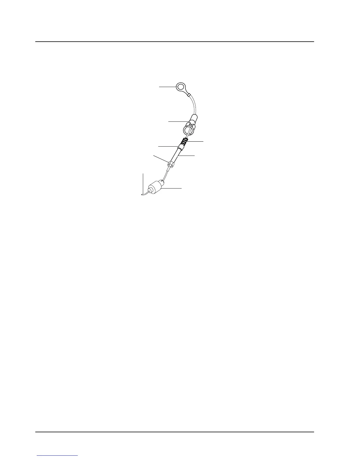
Figure 2-20. Fuseholder Assembly for Yellow and Red Control Cables
• A fuse will need to be placed in-line for both the yellow and red wires; consideration should be
taken when deciding where to place the fuses so that they are easy to inspect. However, they
should also be placed as close as possible to the battery or the vehicle’s ignition switch termi-
nal.
• After choosing the fuse locations, the fuse receptacles need to be installed. This is done by cut-
ting the wire at the chosen location and stripping 1/8-inch of insulation on all loose ends. Make
sure the wire will reach its intended destination.
• Slide the plastic insulator fuseholder over the end of the wire that is connected to the cable kit.
Insert the stripped end of that wire into one of the metal fuse clips, and crimp it closed onto the
exposed wire. Solder it for a better electrical contact.
• On the end of the loose wire, repeat the above crimping and soldering process with the remain-
ing metal fuse clip.
• Temporarily, install the fuse into the fuse clips onto both sides of the fuse. Slide the spring over
the remaining loose end of the wire. The spring should be followed by the plastic insulator fuse-
holder oriented as shown in Figure 2-20. Slide the plastic insulator fuse holder together, by first
making sure the spring slips inside the plastic insulator fuseholder cap. Now, twist the fusehold-
ers until they lock together. After assembly proves successful, remove the fuses until instructed
to install them later.
With the spring and plastic insulator fuseholder cap still in place on the loose portion of the wires
(yellow and red), insert the stripped end of the wire into the spade or ring tongue lug. Crimp and
solder the lug as was done on the metal fuse clips above.
SPADE OR RING
TONGUE LUG
(RING TONGUE
LUG SHOWN)
PLASTIC INSULATOR
FUSE HOLDER CAP
METAL FUSE
CLIPS CRIMP
AND SOLDER
TO WIRE
TO CONTROL
HEAD
SPRING
FUSE
PLASTIC INSULATOR
FUSE HOLDER
MAEPF-21361-O

 Loading...


