HLN6923A October 12, 2005
Options and Accessories Installation: Accessory Connector Assembly Details (P2) (All Models Except 110W) 3-9
It is highly recommended that you attach the correct adapter. Installing the wrong adapter may cause
damage to the data communication circuitry inside your radio. If you are unsure of the pinout of your
former wiring harness, please consult your ASTRO radio installation technician.
3.4.5 Transceiver Rear Accessory Jack Connection
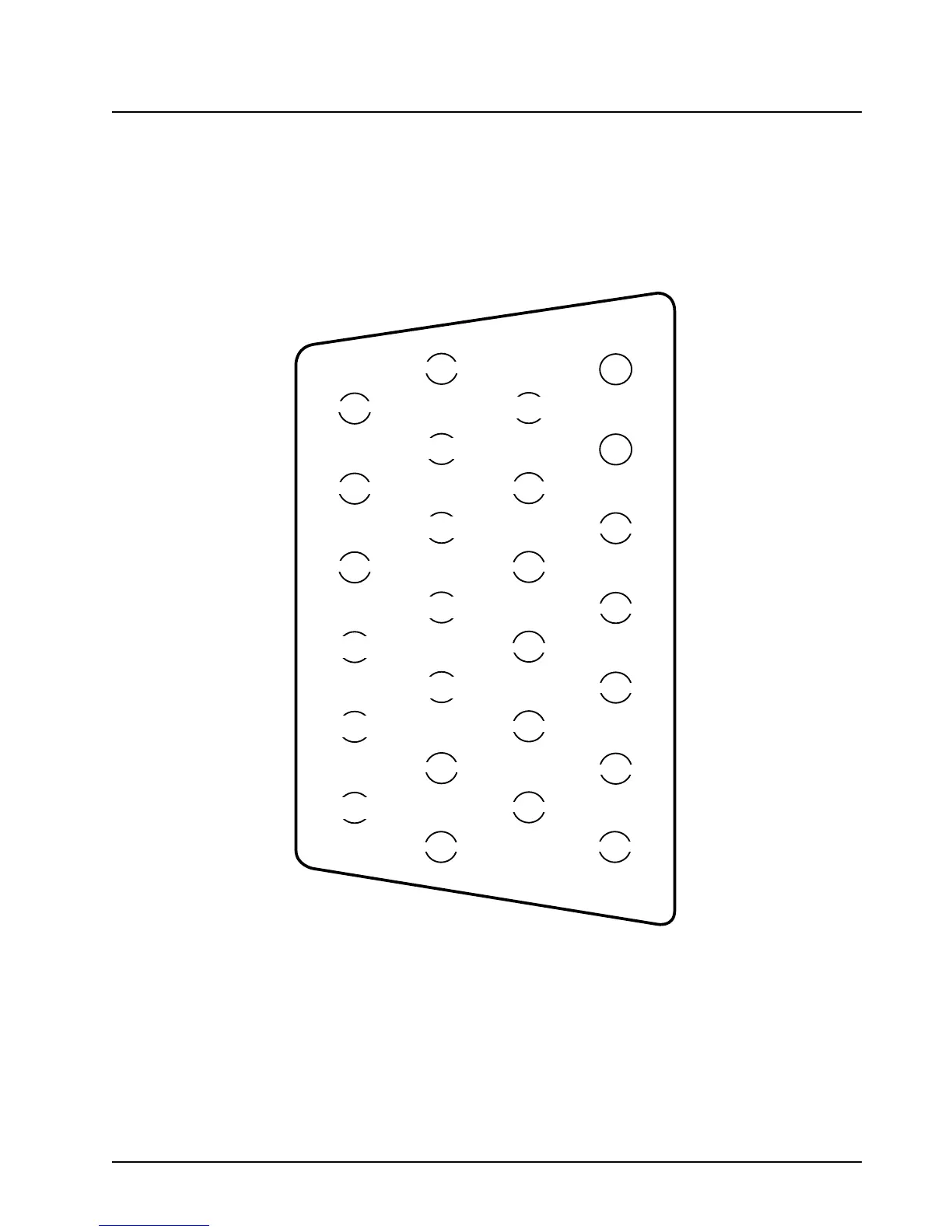
Figure 3-9 shows the complete pin configuration for the J2 rear accessory jack, Figure 3-9 shows the
complete pin configuration for the for the J100 control head rear accessory jack and Table 3-3
explains the functions of each of the pins.
Figure 3-8. Rear Accessory Jack Pin Configuration (J2) (Radio Side)
USB+
USB-
1
7
8
14
13
20
21
26
EMERGENCY
GROUND
GROUND
RX AUDIO
(APCO=[A(rx)]
EXTERNAL
HUB/MONITOR
SWB+
NO CONNECT
VIP
OUT 1
VIP
OUT 2
1-
WIRE
USB PWR
CHAN ACTIVITY
(APCO=[A(p)]
NO CONNECT
NO CONNECT
NO CONNECT
NO CONNECT
NO CONNECT
NO CONNECT
NO CONNECT
NO CONNECT
NO CONNECT
NO CONNECT
AUX PTT
(APCO=[PTT])
AUX MIC
(APCO=[A(tx)]

 Loading...


