HLN6923A October 12, 2005
Options and Accessories Installation: Accessory Connector Assembly Details (P2) (All Models Except 110W) 3-5
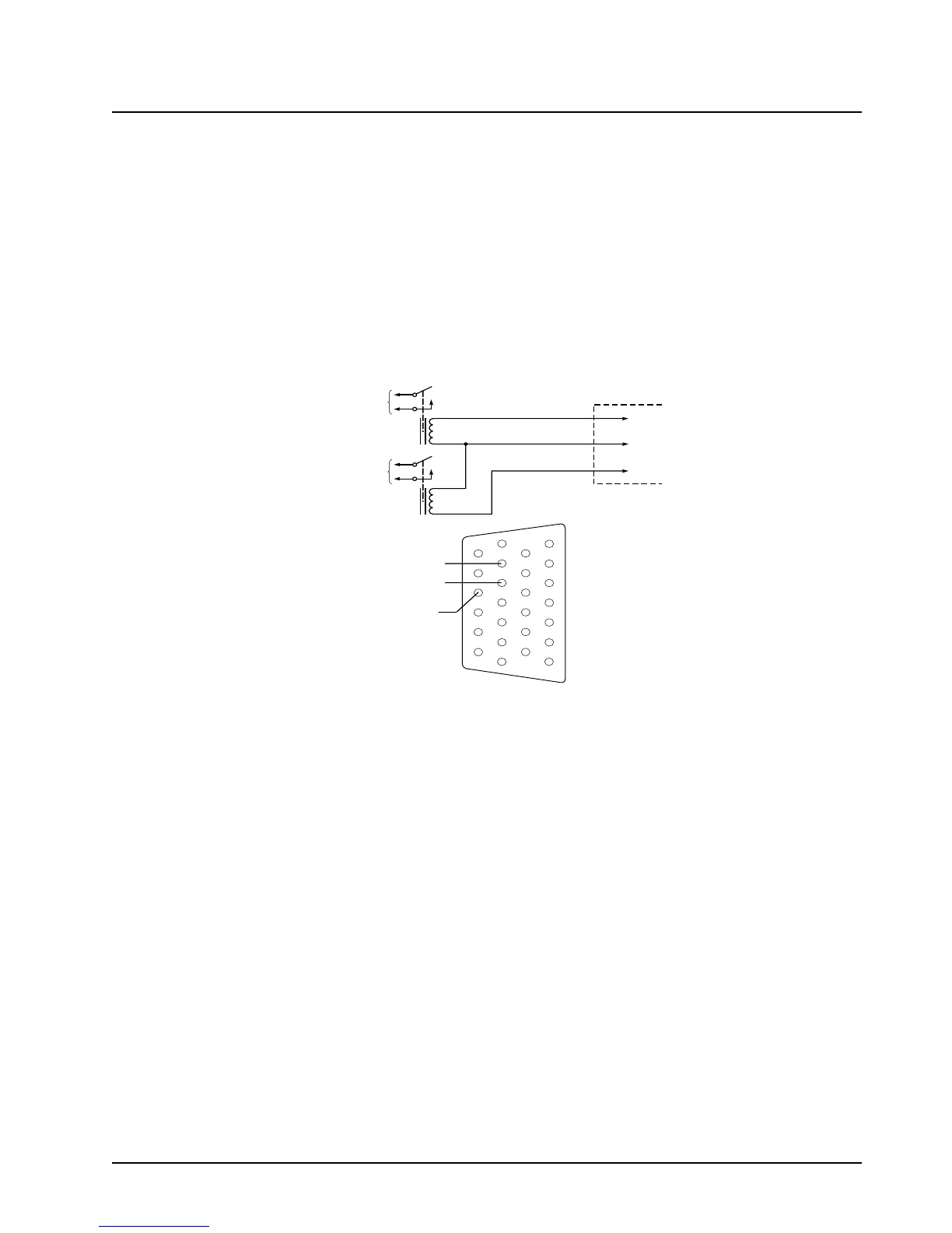
3.3.2 Horn and Lights (External Alarms) Relays
For installations that use the horn/lights option, select a suitable location for mounting (normally
under the dash) and, referring to Figure 3-4, perform the following procedure:
NOTE: The handheld control head can have a horn or light option, but not both. Control wires for
either option should be connected to pins 18 and 24 of the accessory connector.
1. Horn Relay—Connect the relay contacts across the horn ring switch, typically found in the
steering column. Open the accessory cable connector and connect the two control wires
(male pins) into locations 18 and 24 of the connector.
2. Lights Relay—Connect the relay across the headlamp ON/OFF switch, typically found in the
steering column. Open the accessory cable connector and connect the two control wires
(male pins) into locations 19 and 24 of the accessory connector.
Figure 3-4. Horn/Light Wiring Diagram
3.4 Accessory Connector Assembly Details (P2) (All Models Except
110W)
The XTL 2500 accessory connector assembly is mounted on the right rear of the radio, opposite the
antenna and adjacent to the power connector. It is fastened to the radio via jackscrews and held
together by the two cover screws. It is a multi-functional connector that allows for many different
types of adaptations. All approved accessory wires are securely strain-relieved through the exiting
slots at the back of the accessory connector assembly. The terminations that are supplied with all
accessories are designed to be fully engaged and locked into the plug connector (P/N 6680163F01).
They can also be detached for service with the assistance of a terminal removal tool. The accessory
connector assembly can be serviced multiple times for future installation upgrades.
The accessory connector assembly, supplied with every XTL 2500 dash-mounted radio, is equipped
with a 26-pin plug assembly, two covers, two jackscrews, two cover screws, one emergency jumper,
one ignition sense cable assembly, and one speaker pigtail. The jumper is provided to complete the
circuit for emergency mode. If this circuit becomes open, the radio will be set to emergency mode.
CONNECT
ACROSS HORN
RING SWITCH
CONNECT
ACROSS HEAD
LAMP SWITCH
SPST
N.O.
RELAY
12V COIL
12V COIL
VIP OUT 1
SWB+
VIP OUT 2
SPST
N.O.
RELAY
ACCESSORIES
CONNECTOR
PIN 1
PIN 24
PIN 19
SWB+
VIP OUT 2
(LIGHTS)
VIP OUT 1
(HORN)
1
7
8
14
13
20
21
26

 Loading...


