Section 7: 2-1
6881091C63-F
Chapter 2
THEORY OF OPERATION
1.0 Introduction
This chapter provides a detailed theory of operation for the low band circuits in the radio. For details
of the theory of operation and troubleshooting for the associated controller circuits refer to the
controller section of this manual.
2.0 Low Band Receiver Front-End
2.1 Receiver Front-End
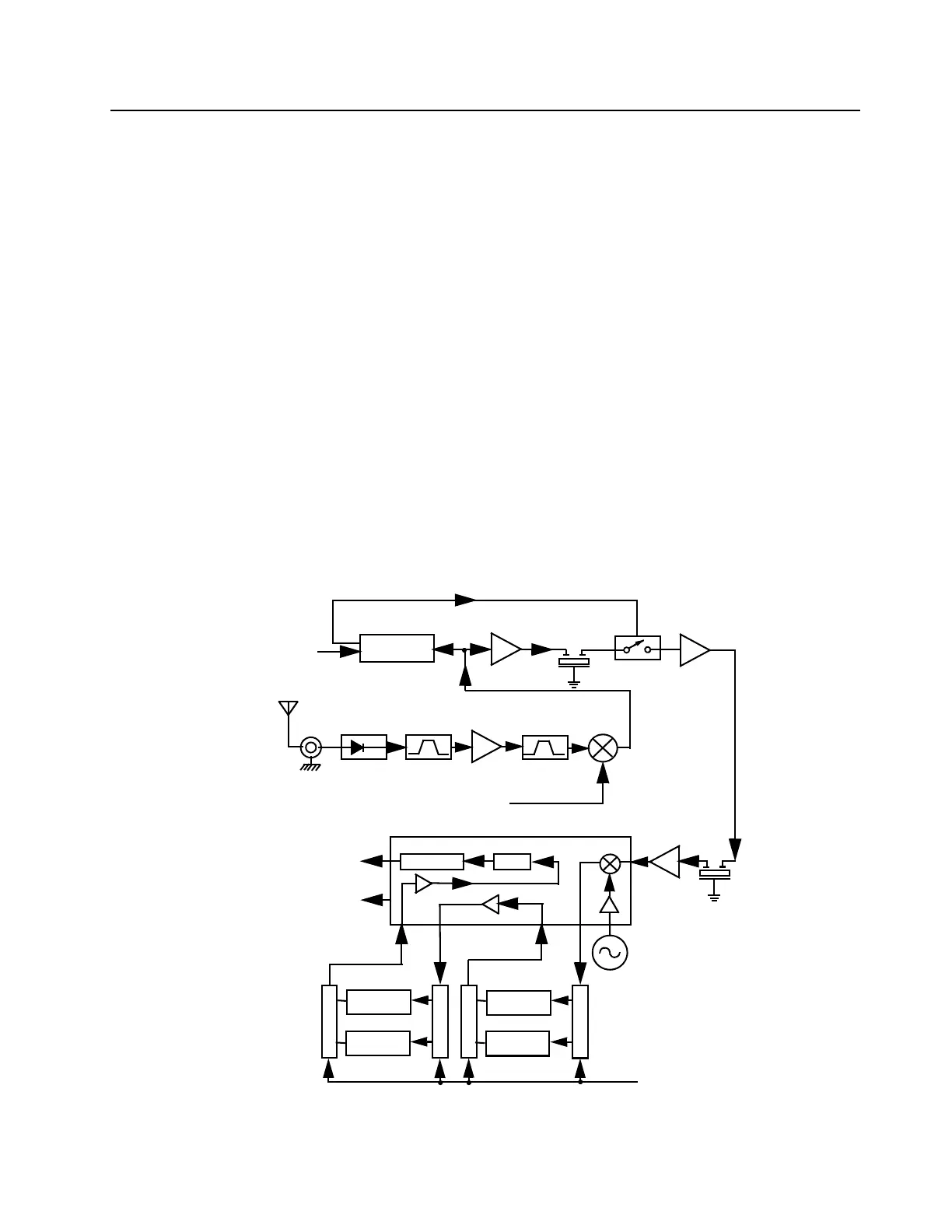
The low band receiver, shown in Figure 7-1, is bandsplit into three ranges depending on radio
model, covering frequencies from 29.7 to 36.0 MHz, 36.0 to 42.0 MHz, or 42.0 to 50.0 MHz. The
circuitry of the three models is identical except for component value differences. The receiver
consists of five major blocks: front-end bandpass filters and pre-amplifier, first mixer, high-IF and
blanker switches, low-IF and receiver back-end, and “Extender” (noise blanker). Two fixed-tuned
bandpass filters perform antenna signal pre-selection. A passive double-balanced mixer converts
the signal to the high-IF of 10.7 MHz. High-side first injection is used.
Figure 7-1 Low Band Receiver Block Diagram
1
Demodulator
Delay
Filter
Mixer
Fixed
Tuned Filter
RF Amp
Tuned Filter
Pin Diode
Antenna
Switch
RF Jack
Antenna
First LO
RXINJ
Recovered Audio
RSSI
IF
Second LO
Crystal
Filter
455kHz Filter
455kHz Filter
455kHz Filter
(12.5kHz)
455kHz Filter
(12.5kHz)
Switch
Switch
Switch
Switch
Limiter
IF Amp
IF Amp
Filter Bank Selection
from Synthesizer IC
Blanker
Noise
Blanking Pulses
Gate
Buffer
Enable
1st
Fixed
(25/20kHz)
BWSELECT
(U1201 Pin 48)
4-pole
(25/20kHz)

 Loading...


