Section 4: 4-1
6881091C63-F
Chapter 4
VHF (136–174 MHZ) 1–25 W PCBS, SCHEMATICS, AND
PARTS LISTS
1.0 Allocation of Schematics and Circuit Boards
1.1 Controller Circuits
The VHF circuits are contained on the printed circuit board (PCB) which also contains the controller
circuits. This chapter shows the schematics for the VHF circuits only. Refer to the controller section
for details of the related controller circuits. The PCB component layouts and the parts lists in this
chapter show both the controller and VHF circuit components. The VHF schematics and the related
PCB and parts list are shown in the tables below.
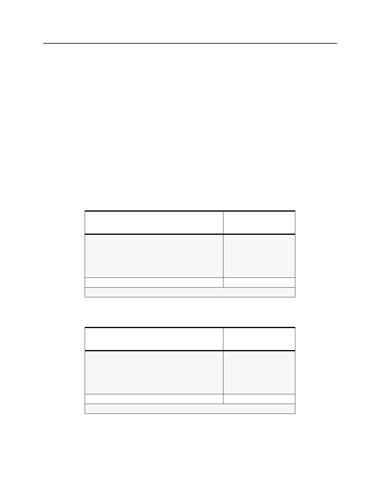
Table 4-1 VHF 1–25 W PCB 8471235L04 Diagrams and Parts Lists
PCB 8471235L04:
Main Board Top Side
Main Board Bottom Side
Page:
4: 4-5
4: 4-6
SCHEMATICS
Power Amplifier 1 – 25 W
FRACN Synthesizer
Voltage Controlled Oscillator
Receiver Front-End
IF
4: 4-7
4: 4-15
4: 4-16
4: 4-17
4: 4-8
Parts List 4: 4-19
Controller version is T9
Table 4-2 VHF 1–25 W PCB 8486172B04 Diagrams and Parts Lists
PCB 8486172B04:
Main Board Top Side
Main Board Bottom Side
Page:
4: 4-12
4: 4-13
SCHEMATICS
Power Amplifier 1 – 25 W
FRACN Synthesizer
Voltage Controlled Oscillator
Receiver Front-End
IF
4: 4-14
4: 4-15
4: 4-16
4: 4-17
4: 4-18
Parts List 4: 4-19
Controller version is T2

 Loading...


