Home
Motorola
Two-Way Radio
CDM Series
Motorola CDM Series User Manual
5
of 2
of 2 ratings
686 pages
Give review
Manual
Specs
To Next Page
To Next Page
To Previous Page
To Previous Page
Loading...
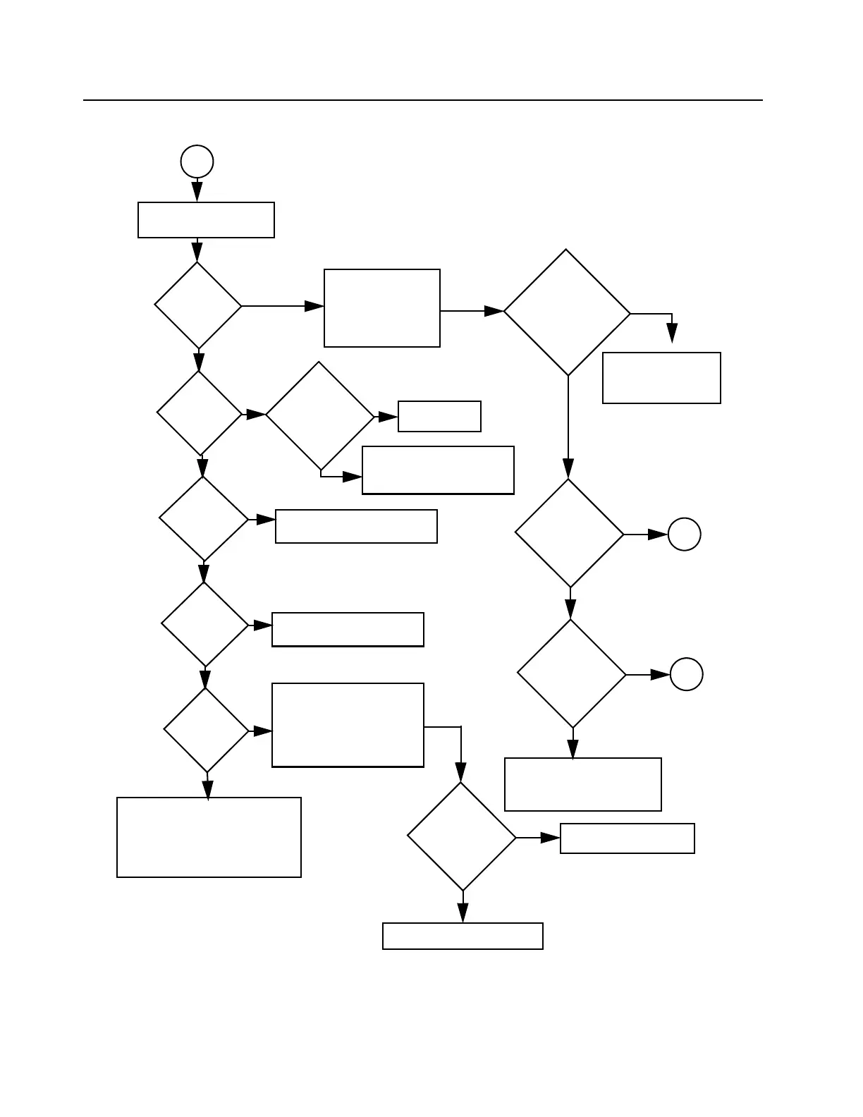
Section 9: 3-2
Troubleshooting Fl
ow Chart for Receiver
6881091C63-F
1.1
T
roubleshooting Flow Chart
for Receiver (Sheet 2 of 2)
IF Signal at
C3101?
No
RF
Signal at
T4051?
RF
Signal at
C4015?
No
No
RF
Signal at
C4025?
No or
Check harmonic filters
L4491-L4493, C4
492, J4401
and ant. switch
D4471, D4472, L4
472.
Check filter between
C4025 & C4009.
Check tuning volt
age
at R4060.
Inject RF into J4401
Is
tuning voltage
OK?
No
Ye
s
Check RF amp (Q4003)
S
tage.
Check filter between
C4015 & T4051.
Ye
s
Check T4051, T4052,
D4051, R4052,
L4008.
Ye
s
1st LO level
OK?
Locked?
Ye
s
Check FGU
Ye
s
T
race IF signal
from C3101 to
Q3101. Check for
bad XT
AL
filter
.
No
Ye
s
IF
signal at Q3102
collector?
Before repla
cing
U3101, check
U3101 volt
ages.
Ye
s
Check for
5VDC
Is 9.3V
present?
Check Supply V
oltage
circuitry
. C
heck U061
1
and U0641.
No
No
No
Check U4501.
Check varactor filter
.
No
Ye
s
Ye
s
Ye
s
A
A
B
weak RF
RF
Signal at
C4009?
505
507
Table of Contents
Product Safety and RF Exposure Compliance
2
Foreword
2
Manual Revisions
2
Computer Software Copyrights
2
Document Copyrights
2
Disclaimer
2
Trademarks
2
Document History
3
Section 1: Service Maintainability
7
Introduction
9
1.0 About this Manual
9
2.0 Warranty and Service Support
9
3.0 Radio Model Information
11
Maintenance
13
1.0 Introduction
13
2.0 Preventive Maintenance
13
3.0 Safe Handling of CMOS and LDMOS
14
4.0 General Repair Procedures and Techniques
14
5.0 Notes For All Schematics and Circuit Boards
17
Service Aids
23
1.0 Recommended Service Tools
23
2.0 Recommended Test Equipment
25
Section 2: Control Head Service Information
27
Overview
29
1.0 CDM750 / PRO3100 Model (GCN6112_)
29
2.0 CDM1250 / PRO5100 Model (GCN6113_)
29
3.0 CDM1550 Series / PRO7100 Model (GCN6114_)
30
4.0 Data Radio Series (GCN6116_)
30
Theory of Operation
31
1.0 Introduction
31
2.0 Control Head (CDM750 / PRO3100)
31
3.0 Control Head (CDM1250 / PRO5100 / CDM1550 Series / PRO7100)
34
Troubleshooting Charts
39
1.0 Control Head CDM750 / PRO3100 Troubleshooting Flow Charts
39
2.0 Control Head CDM1250 / PRO5100 / CDM1550 Series / PRO7100 Troubleshooting Flow Charts
41
Control Head PCBs, Schematics, and Parts Lists
45
1.0 Allocation of Schematics and Circuit Boards
45
2.0 Control Head CDM750 / PRO3100 PCB 8486146B07, Schematics, and Parts Lists
47
Control Head PCB 8486146B07 Parts List†
50
3.0 Control Head CDM1250 / PRO5100 / CDM1550 Series / PRO7100 PCB 8486155B06, Schematics, and Parts Lists
51
Control Head PCB 8486155B06 Parts List†
56
Section 3: Controller Service Maintainability
57
Theory of Operation
59
1.0 Controller Circuits
59
2.0 Controller Board Audio and Signaling Circuits
68
Troubleshooting Charts
79
1.0 Troubleshooting Flow Chart for Controller
79
Controller Schematics and Parts Lists
81
1.0 Allocation of Schematics and Circuit Boards
81
2.0 Controller T2 Schematics and Parts Lists
85
Controller T2 Parts List
90
3.0 Controller T5 Schematics and Parts Lists
92
Controller T5 Parts List
98
4.0 Controller T6/T7/T9 Schematics and Parts Lists
100
Controller T6/7 Parts List
109
Controller T9 Parts List (8471224L01)
111
5.0 Controller T11 Schematics and Parts Lists
113
Controller T11 Parts List
117
6.0 Controller T12 Schematics and Parts Lists
119
Controller T12 Parts List
124
7.0 Controller T12 Schematics and Parts Lists (8471224L04)
126
Controller T12 Parts List (8471224L04)
132
8.0 Controller T6/T7 Schematics and Parts Lists (8471235L06))
136
Controller T6/T7 Parts List (8471235L06)
142
Section 4: VHF (136–174 MHz) 1–25 W Service Information
147
Model Charts and Technical Specifications
149
1.0 VHF (136–174 MHz) 1–25W Model Charts
149
2.0 Technical Specifications
150
Theory of Operation
153
1.0 Introduction
153
2.0 VHF (136–174 MHz) 1–25W Receiver Front-End
153
3.0 VHF (136–174 MHz) 1–25W Transmitter Power Amplifier (PA) 25W
155
4.0 VHF (136–174 MHz) 1–25W Frequency Synthesis
157
Troubleshooting Charts
161
1.0 Troubleshooting Flow Chart for Receiver
161
2.0 Troubleshooting Flow Chart for 25 W Transmitter
163
3.0 Troubleshooting Flow Chart for Synthesizer
166
4.0 Troubleshooting Flow Chart for VCO
167
VHF (136–174 MHz) 1–25 W PCBs, Schematics, and Parts Lists
169
1.0 Allocation of Schematics and Circuit Boards
169
2.0 VHF (136–174 MHz) 1–25 W LDMOS PCB 8471235L04, Schematics, and Parts Lists
173
VHF 1–25 W PCB 8471235L04 Parts List†
177
3.0 VHF (136–174 MHz) 1–25 W PCB 8486172B04, Schematics, and Parts Lists
180
VHF 1–25 W PCB 8486172B04 Parts List†
187
4.0 VHF (136–174 MHz) 1–25 W PCB 8486172B06, Schematics, and Parts Lists
190
VHF 1–25 W PCB 8486172B06 Parts List†
197
5.0 VHF (136–174 MHz) 1–25 W PCB 8486172B07, Schematics, and Parts Lists
200
VHF 1–25 W PCB 8486172B07 Parts List†
204
6.0 VHF (136–174 MHz) 1–25 W PCB 8486172B08, Schematics, and Parts Lists
207
VHF 1–25 W PCB 8486172B08 Parts List†
211
7.0 VHF (136–174 MHz) 1–25 W PCB 8471235L06 Schematics, and Parts Lists
215
VHF 1–25 W PCB 8471235L06 Parts List†
222
Section 5: UHF Band 1 (403–470 MHz) 1–25 W Service Information
227
Model Charts and Technical Specifications
229
1.0 UHF Band 1 (403–470 MHz) 1–25 W Model Charts
229
2.0 Technical Specifications
230
Theory of Operation
233
1.0 Introduction
233
2.0 UHF Band 1 (403–470 MHz) 1–25 W Receiver Front-End
233
3.0 UHF Band 1 (403–470 MHz) 1–25W Transmitter Power Amplifier (PA) 25 W
235
4.0 UHF Band 1 (403–470 MHz) 1–25 W Frequency Synthesis
238
Troubleshooting Charts
243
1.0 Troubleshooting Flow Chart for Receiver
243
2.0 Troubleshooting Flow Chart for 25 W Transmitter
245
3.0 Troubleshooting Flow Chart for Synthesizer
248
4.0 Troubleshooting Flow Chart for VCO
249
5.0 Troubleshooting Flow Chart for PassPort
250
UHF Band 1 (403–470 MHz) 1–25 W PCBs, Schematics, and Parts Lists
251
1.0 Allocation of Schematics and Circuit Boards
251
2.0 UHF Band 1 (403–470 MHz) 1–25 W LDMOS PCB 8471224L03, Schematics, and Parts Lists
253
UHF B1 25–40 W PCB 8471224L03 Parts List†
256
3.0 UHF Band 1 (403–470 MHz) 1–25 W PCB 8485670Z02, Schematics, and Parts Lists
259
UHF B1 1–25 W PCB 8485670Z02 Parts List†
266
4.0 UHF Band 1 (403–470 MHz) 1–25 W PCB 8485670Z03, Schematics, and Parts Lists
269
UHF B1 1–25 W PCB 8485670Z03 Parts List†
276
5.0 UHF Band 1 (403–470 MHz) 1–25 W PCB 8471224L04, Schematics, and Parts Lists
279
UHF 1–25 W PCB 8471224L04 Parts Lists†
286
Section 6: UHF Band 2 (450–512/527 MHz) 1–25W Service Information
291
Model Charts and Technical Specifications
293
1.0 UHF Band 2 (450–512/527 MHz) 1–25 W Model Charts
293
2.0 Technical Specifications
294
Theory of Operation
297
1.0 Introduction
297
2.0 UHF Band 2 (450–512/527 MHz) 1–25W Receiver Front-End
297
3.0 UHF Band 2 (450–512/527 MHz) 1–25 W Transmitter Power Amplifier (PA) 25 W
299
4.0 UHF Band 2 (450–512/527 MHz) 1–25 W Frequency Synthesis
302
Troubleshooting Charts
307
1.0 Troubleshooting Flow Chart for Receiver
307
2.0 Troubleshooting Flow Chart for 25 W Transmitter
309
3.0 Troubleshooting Flow Chart for Synthesizer
312
4.0 Troubleshooting Flow Chart for VCO
313
5.0 Troubleshooting Flow Chart for PassPort
314
UHF Band 2 (450–512/527 MHz) 1–25 W PCBs, Schematics, and Parts Lists
315
1.0 Allocation of Schematics and Circuit Boards
315
2.0 UHF Band 2 (450–512/527 MHz) 1–25 W PCB 8485671Z03, Schematics, and Parts Lists
317
UHF B2 1–25 W PCB 8485671Z03 Parts List†
324
Section 7: Low Band Service Information
329
Model Charts and Technical Specifications
331
1.0 Low Band Range 1 (29.7–36 MHz) Model Charts
331
2.0 Low Band Range 2 (36–42 MHz) Model Charts
332
3.0 Low Band Range 3 (42–50 MHz) Model Charts
333
4.0 Technical Specifications
334
Theory of Operation
337
1.0 Introduction
337
2.0 Low Band Receiver Front-End
337
3.0 Low Band Transmitter Power Amplifier (PA) 60 W
340
4.0 Low Band Frequency Synthesis
343
Troubleshooting Charts
347
1.0 Troubleshooting Flow Chart for Receiver
347
2.0 Troubleshooting Flow Chart for Transmitter
349
3.0 Troubleshooting Flow Chart for Synthesizer
350
4.0 Troubleshooting Flow Chart for VCO
351
Low Band PCBs, Schematics, and Parts Lists
353
1.0 Allocation of Schematics and Circuit Boards
353
2.0 Low Band Range 1 (29.7–36 MHz) PCBs, Schematics, and Parts Lists
357
Low Band R1 PCB 8486206B06 Parts List†
371
Low Band R1 PCB 8486206B08 Parts List†
374
3.0 Low Band Range 2 (36–42 MHz) PCBs, Schematics, and Parts Lists
380
Low Band Range 2 PCB 8486207B07 Parts List
400
Low Band Range 2 PCB 8486207B08 Parts List
406
Low Band Range 2 PCB 8486207B11 Parts List
413
4.0 Low Band Range 3 (42–50 MHz) PCBs, Schematics, and Parts Lists
418
Low Band R3 PCB 8485908Z02 Parts List†
432
Low Band R3 PCB 8485908Z04 Parts List†
435
Low Band Range 3 PCB 8485908Z05 Parts List
441
Low Band Range 3 PCB 8485908Z08 Parts List
448
Section 8: VHF (136–174 MHz) 25–45 W Bipolar Service Information
453
Model Charts and Technical Specifications
455
1.0 VHF (136–174 MHz) 25–45 W Bipolar Model Charts
455
2.0 Technical Specifications
456
Theory of Operation
459
1.0 Introduction
459
2.0 VHF (136–174 MHz) 25–45 W Bipolar Receiver Front-End
459
3.0 VHF (136–174 MHz) 25–45 W Bipolar Transmitter Power Amplifier (PA) 45 W
461
4.0 VHF (136–174 MHz) 25–45 W Bipolar Frequency Synthesis
463
Troubleshooting Charts
467
1.0 Troubleshooting Flow Chart for Receiver
467
2.0 Troubleshooting Flow Chart for 45 W Transmitter
469
3.0 Troubleshooting Flow Chart for Synthesizer
471
4.0 Troubleshooting Flow Chart for VCO
472
VHF (136–174 MHz) 25–45 W Bipolar PCBs, Schematics, and Parts Lists
473
1.0 Allocation of Schematics and Circuit Boards
473
2.0 VHF (136–174 MHz) 25–45 W Bipolar PCB 8486140B12, Schematics, and Parts Lists
475
VHF 25–45 W PCB 8486140B12 Parts List†
482
3.0 VHF (136–174 MHz) 25–45 W Bipolar PCB 8486140B13, Schematics, and Parts Lists
485
VHF 25–45 W PCB 8486140B13 Parts List†
488
Section 9: UHF Band 1 (403–470 MHz) 25–40 W Bipolar Service Information
491
Model Charts and Technical Specifications
493
1.0 UHF Band 1 (403–470 MHz) 25–40 W Bipolar Model Charts
493
2.0 Technical Specifications
494
Theory of Operation
497
1.0 Introduction
497
2.0 UHF Band 1 (403–470 MHz) 25–40 W Bipolar Receiver Front-End
497
3.0 UHF Band 1 (403–470 MHz) 25–40 W Bipolar Transmitter Power Amplifier (PA) 40W
499
4.0 UHF Band 1 (403–470 MHz) 25–40 W Bipolar Frequency Synthesis
501
Troubleshooting Charts
505
1.0 Troubleshooting Flow Chart for Receiver
505
2.0 Troubleshooting Flow Chart for 40W Transmitter
507
3.0 Troubleshooting Flow Chart for Synthesizer
508
4.0 Troubleshooting Flow Chart for VCO
509
5.0 Troubleshooting Flow Chart for PassPort
510
UHF Band 1 (403–470 MHz) 25–40 W Bipolar PCBs, Schematics, and Parts Lists
511
1.0 Allocation of Schematics and Circuit Boards
511
2.0 UHF Band 1 (403–470 MHz) 25–40 W Bipolar PCB 8480643Z06, Schematics, and Parts Lists
513
UHF B1 25–40 W PCB 8480643Z06 Parts List†
520
Section 10: UHF Band 2 (450–512/520 MHz) 25–40W Bipolar Service Information
525
Model Charts and Technical Specifications
527
1.0 UHF Band 2 (450–512/520 MHz) 25–40 W Bipolar Model Charts
527
2.0 Technical Specifications
528
Theory of Operation
531
1.0 Introduction
531
2.0 UHF Band 2 (450–512/520 MHz) 25–40 W Bipolar Receiver Front- End
531
3.0 UHF Band 2 (450–512/520 MHz) 25–40 W Bipolar Transmitter Power Amplifier (PA) 40W
533
4.0 UHF Band 2 (450–512/520 MHz) 25–40 W Bipolar Frequency Synthesis
535
Troubleshooting Charts
539
1.0 Troubleshooting Flow Chart for Receiver
539
2.0 Troubleshooting Flow Chart for 40 W Transmitter
541
3.0 Troubleshooting Flow Chart for Synthesizer
542
4.0 Troubleshooting Flow Chart for VCO
543
5.0 Troubleshooting Flow Chart for PassPort
544
UHF Band 2 (450–512/520 MHz) 25–40 W Bipolar PCBs, Schematics, and Parts Lists
545
1.0 Allocation of Schematics and Circuit Boards
545
2.0 UHF Band 2 (450–512/520 MHz) 25–40 W Bipolar PCB 8480645Z04, Schematics, and Parts Lists
547
UHF B2 25–40 W PCB 8480645Z04 Parts List†
554
Section 11: VHF (136–174 MHz) 25–45 W LDMOS Service Information
559
Model Charts and Technical Specifications
561
1.0 VHF (136–174 MHz) 25–45 W LDMOS Model Charts
561
2.0 Technical Specifications
562
Theory of Operation
565
1.0 Introduction
565
2.0 VHF (136–174 MHz) 25–45 W LDMOS Receiver Front-End
565
3.0 VHF (136–174 MHz) 25–45W LDMOS Transmitter Power Amplifier (PA) 45 W
567
4.0 VHF (136–174 MHz) 25–45 W LDMOS Frequency Synthesis
569
Troubleshooting Charts
573
1.0 Troubleshooting Flow Chart for Receiver
573
2.0 Troubleshooting Flow Chart for 45 W Transmitter
575
3.0 Troubleshooting Flow Chart for Synthesizer
578
4.0 Troubleshooting Flow Chart for VCO
579
VHF (136–174 MHz) 25–45 W LDMOS PCBs, Schematics, and Parts Lists
581
1.0 Allocation of Schematics and Circuit Boards
581
2.0 VHF (136–174 MHz) 25–45 W LDMOS PCB 8486140B15, Schematics, and Parts Lists
583
VHF 25–45 W PCB 8486140B15 Parts List†
590
4.0 VHF (136–174 MHz) 25–45 W LDMOS PCB 8471234L02, Schematics, and Parts Lists
593
VHF PCB 8471234L02 Parts List
600
Section 12: UHF Band 1 (403–470 MHz) 25–40 W LDMOS Service Information
603
Model Charts and Technical Specifications
605
1.0 UHF Band 1 (403–470 MHz) 25–40 W LDMOS Model Charts
605
2.0 Technical Specifications
606
Theory of Operation
609
1.0 Introduction
609
2.0 UHF Band 1 (403–470 MHz) 25–40 W LDMOS Receiver Front-End
609
3.0 UHF Band 1 (403–470 MHz) 25–40 W LDMOS Transmitter Power Amplifier (PA) 40W
611
4.0 UHF Band 1 (403–470 MHz) 25–40 W LDMOS Frequency Synthesis
613
Troubleshooting Charts
617
1.0 Troubleshooting Flow Chart for Receiver
617
2.0 Troubleshooting Flow Chart for 40 W Transmitter
619
3.0 Troubleshooting Flow Chart for Synthesizer
621
4.0 Troubleshooting Flow Chart for VCO
622
5.0 Troubleshooting Flow Chart for PassPort
623
UHF Band 1 (403–470 MHz) 25–40 W LDMOS PCBs, Schematics, and Parts Lists
625
1.0 Allocation of Schematics and Circuit Boards
625
2.0 UHF Band 1 (403–470 MHz) 25–40 W LDMOS PCB 8486127Z01, Schematics, and Parts Lists
627
UHF B1 25–40 W PCB 8486127Z01 Parts List†
634
3.0 UHF Band 1 (403–470 MHz) 25–40 W LDMOS PCB 8471223L02, Schematics, and Parts Lists
638
UHF B1 25–40 W PCB 8471223L02 Parts List
645
Section 13: UHF Band 2 (450–512/520 MHz) 25–40 W LDMOS Service Information
649
Model Charts and Technical Specifications
651
1.0 UHF Band 2 (450–512/520 MHz) 25–40 W LDMOS Model Charts
651
2.0 Technical Specifications
652
Theory of Operation
655
1.0 Introduction
655
2.0 UHF Band 2 (450–512/520 MHz) 25–40 W LDMOS Receiver Front- End
655
3.0 UHF Band 2 (450–512/520 MHz) 25–40 W LDMOS Transmitter Power Amplifier (PA) 40 W
657
4.0 UHF Band 2 (450–512/520 MHz) 25–40 W LDMOS Frequency Synthesis
660
Troubleshooting Charts
665
1.0 Troubleshooting Flow Chart for Receiver
665
2.0 Troubleshooting Flow Chart for 40 W Transmitter
667
3.0 Troubleshooting Flow Chart for Synthesizer
668
4.0 Troubleshooting Flow Chart for VCO
669
5.0 Troubleshooting Flow Chart for PassPort
670
UHF Band 2 (450–512/520 MHz) 25–40 W LDMOS PCBs, Schematics, and Parts Lists
671
1.0 Allocation of Schematics and Circuit Boards
671
2.0 UHF Band 2 (450–512/520 MHz) 25–40 W LDMOS PCB 8486250Z02, Schematics, and Parts Lists
673
UHF B2 25-40 W PCB 8486250Z02 Parts List†
680
Appendix A Replacement Parts Ordering
685
A.1 Basic Ordering Information
685
A.2 Motorola Online
685
A.3 Mail Orders
685
A.4 Telephone Orders
685
A.5 Fax Orders
685
A.6 Parts Identification
686
A.7 Product Customer Service
686
Other manuals for Motorola CDM Series
Service Manual
178 pages
Basic Service Manual
92 pages
Service & Installation Manual
32 pages
5
Based on 2 ratings
Ask a question
Give review
Questions and Answers:
Need help?
Do you have a question about the Motorola CDM Series and is the answer not in the manual?
Ask a question
Motorola CDM Series Specifications
General
Frequency Range (VHF)
136-174 MHz
Number of Channels
16
Frequency
VHF
Frequency Range (UHF)
403-470 MHz
Battery Life
8 hours (typical)
Related product manuals
Motorola CDM750
686 pages
Motorola CDM1250
686 pages
Motorola CDM1550 LS
5 pages
Motorola CDM1550-LS+
114 pages
Motorola CP100
62 pages
Motorola CP185
120 pages
Motorola CP200
88 pages
Motorola CP150
252 pages
Motorola clp446
46 pages
Motorola CLS1410
72 pages
Motorola CLS1110
66 pages
Motorola CLP446e
792 pages