December, 2009 68009328001-A
2-2 Theory Of Operation: Major Assemblies
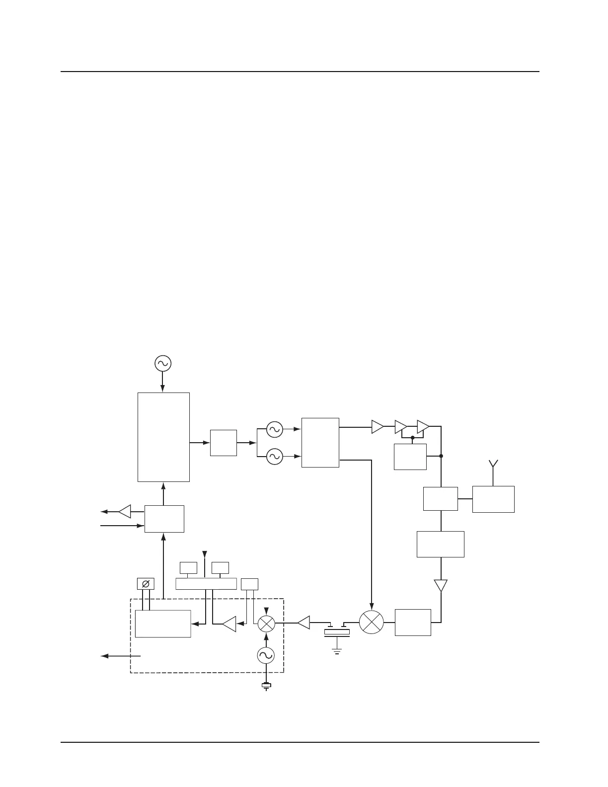
The IFIC is a low-voltage monolithic FM IF system incorporating a mixer/oscillator, two limiting IF
amplifiers, quadrature detector, logarithmic received signal strength indicator (RSSI), voltage
regulator and audio, and RSSI Op Amps. The second LO frequency, 44.395 MHz, is determined by a
crystal oscillator. The second mixer converts the 44.85 MHz high IF frequency to 455 kHz.
Additional IF selectivity is provided by two ceramic filters. The first ceramic filter is a 4-pole filter used
between the second mixer and IF amp. The second ceramic filter is a 6-pole filter and is used
between the IF amp and the limiter input. For the second ceramic filter, a wider filter is used for 20/25
kHz channel spacing, and a narrower filter is used for 12.5 kHz channels.
A ceramic resonator provides phases vs. frequency characteristic required by the quadrature
detector, with 90 degree phase shift occurring at 455 kHz. The output of the IFIC is the recovered
audio signal which is fed to the audio IC for amplification and signal conditioning. The output of the
audio IC is injecting into the audio PA which drives the 24 Ohm speaker.
2.2.2 Transmitter
• When the radio is transmitting, microphone audio is passed through the audio IC, where pre-
emphasis and low-pass (splatter) filtering are done. The output of the audio IC is used to
modulate the TX VCO, which creates the modulated carrier. The modulated carrier is then
amplified by the pre-driver and power amplifier circuit, which transmits the signal under
dynamic power control
Figure 2-2. Transceiver Block Diagram
Crystal
Filter
Filter
Filter
Filter
Mixer
IF Amp
VCOBIC
Loop
Filter
Rx VCO
Circuit
Tx VCO
Circuit
Ref. Osc.
Rx Out
Tx Out
Audio IC
Mic
Audio PA
Spkr
Predriver
Switch
T/R
Rx
Tx
Module
PA
Demodulator
Recovered Audio
RSSI
Ceramic
Resonator
Cer Fltr
Switching
4E
6E
6G
BW_SEL
Preselector
Frac N
Mod
Power
Cntr
Harmonic
LNA
Image
IF IC

 Loading...