December, 2009 68009328001-A
6-12 Full Keypad Model Disassembly and Re-assembly: Disassembling and Re-assembling the Radio — General
6.4.2.5 Chassis Assembly/Re-assembly
1. Replace the battery contact seal (if necessary) surrounding the battery contact (Figure 6-16).
2. Remove the old Interface Pad from the chassis by scraping off the pad and adhesive with a
straight razor. Use rubbing alcohol and a cloth to completely remove the adhesive from the
chassis surface. With the chassis clean and dry, add a new Interface Pad to the chassis.
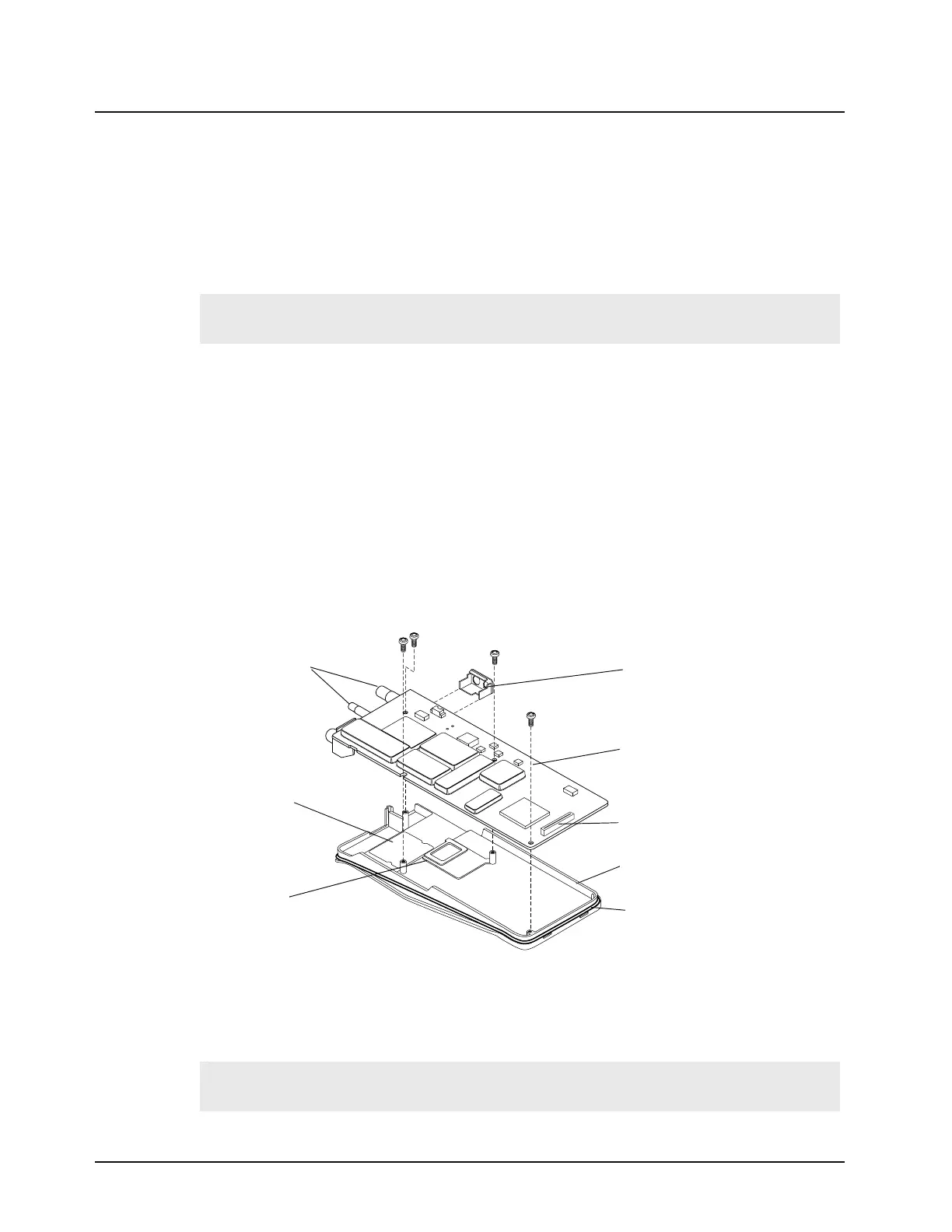
3. Place the main circuit board straight down on top of the chassis with the frequency and volume
switches facing down (Figure 6-16).
4. Use the T6 Torx screwdriver to fasten the screws holding the main board to the chassis. Tighten
to 3.7 - 3.9 in/lb.
5. Replacing the O-ring.
a. If you have the older chassis (2786389Z01) use the older O-ring (3286431Z02). Position
the O-ring in the top groove by the volume/frequency switches. Stretch the O-ring to
place it into the retaining groove at the bottom end of the chassis.
b. If you have the newer chassis (2786389Z02) use the newer O-ring (3286431Z05).
Position the O-ring with the plug on the right side (speaker connector side). Push the
plug all the way into the chassis slot until it is touching the chassis flange. Repeat for the
left side. Stretch the O-ring to place it into the retaining groove at the top and bottom end
of the chassis.
6. Check that the O-ring is not twisted and being held by the top and bottom chassis groves.
6.4.2.6 Chassis and Front Cover Re-assembly
1. Dress and connect the speaker wires..
Note:
Be sure the battery contact seal protrudes through the chassis and is not pinched under the
chassis.
Figure 6-16. Main Board onto Chassis Re-assembly
Note:
Care should be taken when dressing the speaker and microphone wires to avoid pinching
between the accessory connector and housing.
Main Board
Radio Chassis
Flex Cable Connector
Battery Contact Seal
Interface Pad
Frequency &
Volume Switches
Audio Jack Shroud
(Replace after Plugging
in Speaker and Mic)
O-Ring

 Loading...