68009328001-A December, 2009
Radio Alignment Procedures: Transmitter Alignment Options 5-3
5.3.1 Initial Test Equipment Control Settings
The initial test equipment control settings are listed in Table 5-1.
5.4 Transmitter Alignment Options
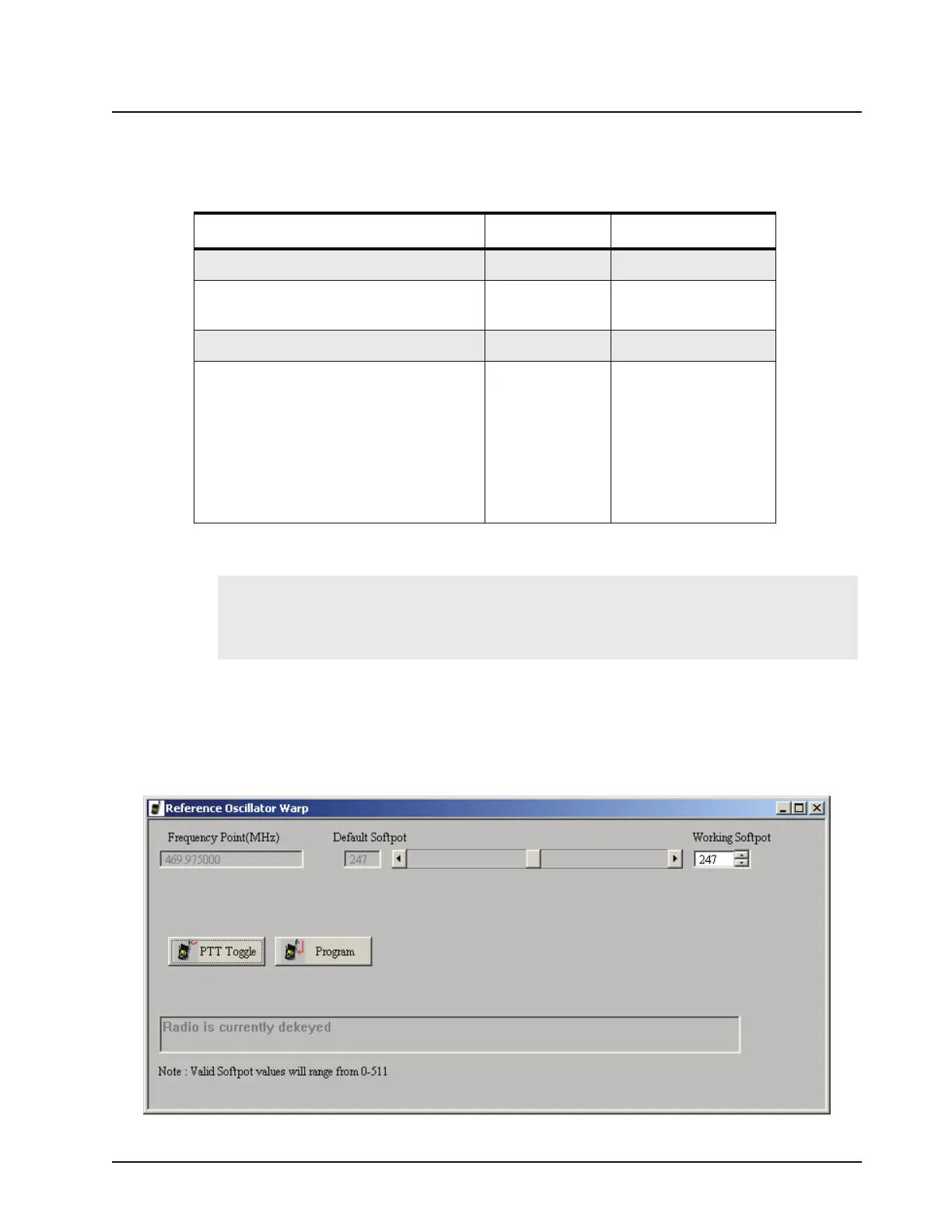
5.4.1 Reference Oscillator Warp
This is an important operation which affects all deviation values such as DTMF, MDC1200 Signaling
etc. The frequency will drift if not warped properly. Perform this operation prior to all other transmit
tuning operations in order to minimize heating and because of the impact of warp on signaling
operations.
Table 5-1. Initial Equipment Control Settings
Service Monitor Test Set Power Supply
Monitor Mode: Power Monitor Speaker set: A Voltage: 13.2 Vdc
RF Attenuation: -70 Speaker/load:
Speaker
DC on/standby:
Standby
AM, CW, FM: FM PTT: OFF Volt Range: 20 V
Oscilloscope Source: Mod
Oscilloscope Horizontal: 10 mSec/Div
Oscilloscope Vertical: 2.5 kHz/Div
Oscilloscope Trigger: Auto
Monitor Image: Hi
Monitor BW: Nar
Monitor Squelch: mid CW
Monitor Volume: 1/4 CW
Current: 20 A
Note:
When checking the RF power output of the radio with a test set, always use a pad of
at least 30 dB attached to the radio end of the RF cable. This will avoid an RF
mismatch and ensure a stable RF reading that will not change with varying lengths of
connecting cable.
Figure 5-3. Reference Oscillator Warp Window

 Loading...