68009328001-A December, 2009
Limited Keypad Model Disassembly and Re-assembly: Disassembling and Re-assembling the Radio — General 7-13
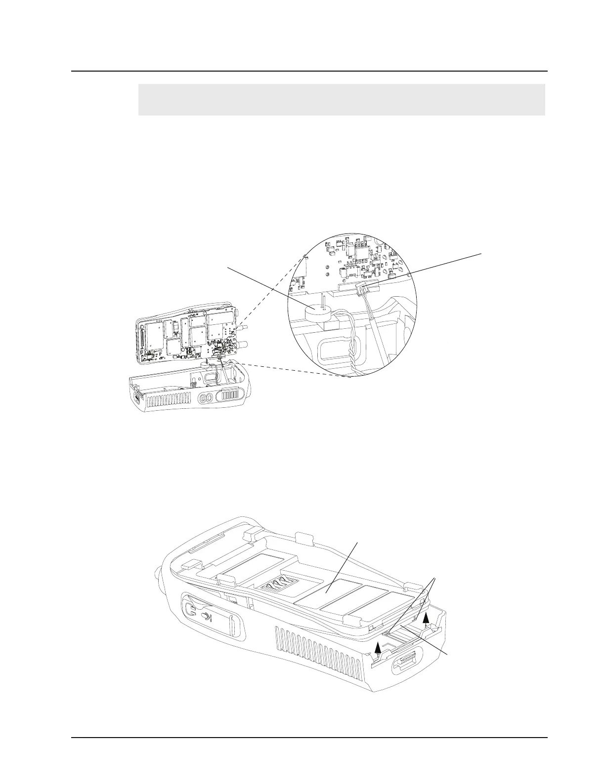
a. Connect the speaker wire assembly into the 2-pin connector on the main board and
bend the wires at the board connector so the wires are positioned toward the top of the
radio (Figure 7-17).
b. Connect the microphone wire assembly into the two hole socket on the main board and
bend the wires at the board connector so the wires are positioned toward the top of the
radio (Figure 7-17).
c. Slide the audio jack shroud onto accessory connector
(Figure 7-17).
2. Position the radio (Figure 7-18) and reconnect the flex cable connector from the keyboard into the
connector located on the bottom of the main board, pushing up the 2 end tabs.
3. Slide the volume potentiometer and frequency switch shafts into their respective holes in the front
cover. Look through the accessory connector opening to make certain that the wires are not
pinched, between the shroud and housing.
Note:
Ensure that the plug orientation is correct with the exposed pins in the wire casing facing
upward and fully plugged in.
Figure 7-17. Microphone and Speaker Re-assembly
Figure 7-18. Keyboard Flex Cable Connection
Speaker Connector
Microphone
Connector
Radio Chassis
Flex Connector
End Tabs

 Loading...