viii List of Figures
List of Figures
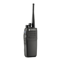
Figure 1-1. Limited Keypad Model..........................................................................................................1-2
Figure 1-2. Non Keypad Model...............................................................................................................1-3
Figure 1-3. Portable Radio Model Numbering Scheme..........................................................................1-4
Figure 2-1. Programming, Testing and Alignment Cable........................................................................2-3
Figure 2-2. Pin Layout of Side Connector ..............................................................................................2-4
Figure 3-1. DMR Radio Transmitter and Receiver Testing Setup...........................................................3-2
Figure 3-2. Battery Check Test Mode Display ........................................................................................3-9
Figure 4-1. CPS Programming Setup.....................................................................................................4-1
Figure 4-2. Radio Tuning Equipment Setup ...........................................................................................4-2
Figure 4-3. RF Plug disassembly ...........................................................................................................4-3
Figure 4-4. RF Adaptor insertion ............................................................................................................4-3
Figure 4-5. RF Adaptor screw ................................................................................................................4-4
Figure 4-6. RF Connector.......................................................................................................................4-4
Figure 5-1. Battery removal....................................................................................................................5-6
Figure 5-2. Battery removal....................................................................................................................5-6
Figure 5-3. Antenna removal..................................................................................................................5-7
Figure 5-4. Volume and Channel Knob removal.....................................................................................5-8
Figure 5-5. Front Kit-Back Kit Screw removal ........................................................................................5-8
Figure 5-6. Back Kit disassembly ...........................................................................................................5-9
Figure 5-7. Back Kit removal ................................................................................................................5-10
Figure 5-8. Disconnecting the interface UC-audio flex and keypad-display flex (Limited Keypad Model) 5-
11
Figure 5-9. Disconnecting the UC-audio flex (Non Keypad Model)...................................................... 5-11
Figure 5-10. Top control seal removal ....................................................................................................5-12
Figure 5-11. Back Kit disassembly .........................................................................................................5-12
Figure 5-12. Battery contact seal removal..............................................................................................5-13
Figure 5-13. UC-audio flex removal........................................................................................................5-14
Figure 5-14. K18 screw removal.............................................................................................................5-14
Figure 5-15. Display flex removal ...........................................................................................................5-15
Figure 5-16. Keypad removal .................................................................................................................5-15
Figure 5-17. PTT retainer removal..........................................................................................................5-16
Figure 5-18. Side button removal ...........................................................................................................5-16
Figure 5-19. UC escutcheon removal.....................................................................................................5-17
Figure 5-20. UC-audio flex removal........................................................................................................5-18
Figure 5-21. Speaker retainer screw removal.........................................................................................5-18
Figure 5-22. Speaker retainer removal...................................................................................................5-19
Figure 5-23. Speaker assembly..............................................................................................................5-20
Figure 5-24. UC-audio flex .....................................................................................................................5-20
Figure 5-25. UC escutcheon...................................................................................................................5-21
Figure 5-26. Speaker retainer reassembly........................................................................................
......5-21
Figure
5-27.
Side button reassembly......................................................................................................5-22
Figure 5-28. PTT retainer reassembly....................................................................................................5-22
Figure 5-29. Display module reassembly ...............................................................................................5-23
Figure 5-30. Keypad reassembly............................................................................................................5-23
Figure 5-31. Keypad board reassembly..................................................................................................5-24
Figure 5-32. Display flex reassembly .....................................................................................................5-24
Figure 5-33. Speaker retainer reassembly..............................................................................................5-25
Figure 5-34. UC-Audio Flex Pad Reassembly........................................................................................5-25
Figure 5-35. Thermal pad.......................................................................................................................5-26
Figure 5-36. Battery contact seal reassembly ........................................................................................5-27

 Loading...


