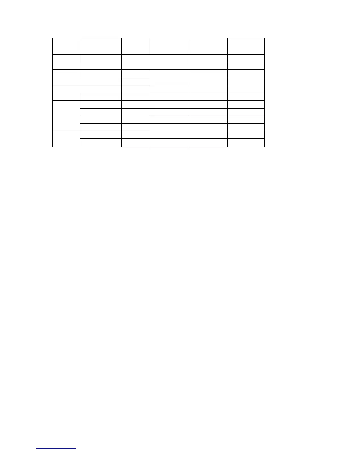
NO. OF
BEEPS TEST CHANNEL VHF UHF BAND 1 UHF BAND 2 800
TX #1 136.025 403.100 450.025 806.0125
RX #1 136.075 403.150 450.075 851.0625
TX #2 142.125 424.850 465.225 815.0125
RX #2 142.075 424.900 465.275 860.0625
TX #3 154.225 438.050 475.225 824.9875
RX #3 154.275 438.100 475.275 869.9375
TX #4 160.125 444.050 484.975 851.0125
RX #4 160.175 444.100 485.025 851.0625
TX #5 168.075 456.350 500.275 860.0125
RX #5 168.125 456.400 500.225 860.0625
TX #6 173.975 463.700 511.975 869.9875
RX #6 173.925 463.750 511.925 869.9375
Table 40-6. Test Frequencies, HT 1000 Radios
1
2
3
4
5
6
(e) Test the on/off volume potentiometer/switch by
rotating the potentiometer clockwise and counter
clockwise. The loudness of tone beeps will
increase and decrease accordingly.
NOTE
During test mode, the volume level is not regulated
to the same limits as during normal radio operation.
To exit test mode, turn the radio off then back on.
3. RF Test Mode, MT 2000, MTS 2000, and MTX
Series Radios
When the MT 2000, MTS 2000, or MTX series radio
is operating in its normal environment, the radio's
microcomputer controls the RF channel selection,
transmitter key-up, and receiver muting. However,
when the unit is on the bench for testing, alignment,
or repair, it is removed from its normal environment.
It cannot receive commands from its system and,
therefore, the internal microcomputer will not key the
transmitter nor unmute the receiver. This prevents
the use of normal tune-up procedures. To solve this
problem a special routine, called TEST MODE or “air
test,” has been incorporated in the radio.
To enter test mode:
(a) Turn the radio on.
(b) After the self test is complete, press the monitor
button (side button 3, SB3) five times in succes-
sion, within 10 seconds.
(c) After “RF TEST” appears (on 14-character dis-
plays) or “RF TST” appears (on 6-character
displays), press the orange button on top of the
radio once. “1 CSQ” appears, indicating: test fre-
quency 1, carrier squelch mode.
(d) Each additional press of SB3 will advance to the
next test channel. (Refer to Table 40-8.)
(e) Pressing SB2 will scroll through and access test
environments as shown in Table 40-7.
NOTES
1. Transmit into a load when keying a radio
under test.
2. Radios without display indicate test-environ-
ment function by emitting a corresponding
number of beeps. See Table 40-7.
4. Control Head Test Mode, MT 2000, MTS 2000,
and MTX Series Radios
To check the display, the buttons, and the switches,
perform the following tests:
(a) Turn radio on
(b) After the self test is complete, press the monitor
button (side button 3, SB3) five times in succes-
sion, within 10 seconds.
(c) After ”RF TEST” appears on the display, press
side button 1 (SB1), “CH TEST” (14-character
radio) or “CH TST” (6-character radio) appears
on the display.
(d) Next, press and hold the orange button on top of
the radio; all segments on the display will light,
and the LED on the control top will illuminate a
yellowish color.
(e) Release the orange button; ”3/0” appears, which
indicates that switch 3 is in the open condition.
(f) Press the orange button again; “3/1” appears,
which indicates that switch 3 is in the closed
condition.
(g) Rotate the mode selector knob; ”4/0” thru ”4/15”
appears, which indicates that knob 4 is in mode
position 1 thru 15.
(h) Rotate the concentric switch; ”65/0” and “65/1”
appears.
(i) Rotate the volume control; “2/0” thru “2/255”
appears.
(j) Press SB1, view “96/1”; release, view “96/0”
(k) Press SB2, view “97/1”; release, view “97/0”
6

 Loading...


