21
E. Reassembly
Reassembly is the reverse of disassembly. Some
suggestions and illustrations are provided to help you
more easily reassemble the radio.
1. Keypad/Display Board
(front display model radios only)
a. If applicable, replace the rubber keypad.
b. Place the keypad/display board into the front
cover housing at an angle such that the three
small slots on the edge of the board slide under
the three mating retaining tabs. Ensure that the
board slides under the tabs.
c. Near the three larger slots on the other side of
the board, use finger pressure to push and
press that side of the board down until it snaps
into place under the three large retaining tabs.
2. Front Cover Assembly
a. Place the speaker and microphone into their
respective positions in the front cover. Make
sure that the speaker is seated properly in the
recessed area provided.
b. Press the rubber microphone boot into its
respective recessed area in the front cover
housing. The little rubber flap in the back of the
rubber boot should fold up to cover the micro-
phone insertion opening.
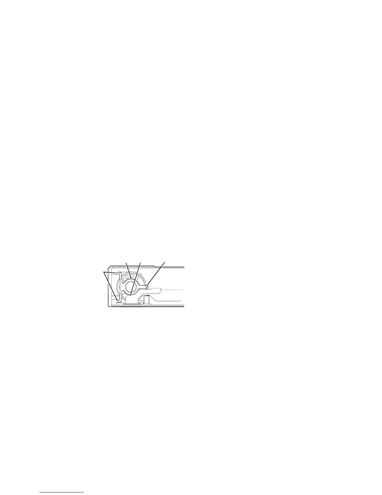
c. Reinstall the speaker retainer bracket (see
Figure 40-13).
(1) Position the spring bracket over the speak-
er, and toward the top of the front cover
housing; insert the appropriate two legs of
the bracket into their respective slots
(2) Grasp the center portion of the spring
bracket (ring area) with thumb and
forefinger.
(3) While holding the ring area of the spring
bracket at approximately the same height
as the speaker's base, push the remaining
leg down and into its respective slot.
d. Orient the edge connector so that its gold con-
tacts face the gold contacts of the housing.
Align the edge connector with the respective
slots in the housing, and slide the connector
down into place. Ensure that the edge connec-
tor is fully seated into position.
e. On top display model radios only, seat the dis-
play board by inserting the two display board
tabs into their mating slots in the front cover
housing. Push the top of the display board
toward the top of the radio until the front cover
housing retaining tabs engage the display
board and secure it into position.
3. Chassis
Inside of the chassis where the RF board fits is a
protruding block that functions as the PA heatsink.
To help provide maximum heat transfer, ensure that
the PA heatsink block (top surface) is coated with a
thin film of thermal compound (Motorola part
number 1110022A55).
Place the RF board and controller board into the
chassis. Ensure that the plastic cover that more
rigidly holds the two boards together is snapped into
place.
4. Control Top
a. Reinstall the switches and LED into the switch
housing.
b. Reinstall the switch housing cover onto the
switch housing by sliding tabs 4 and 5 of the
cover into their respective clips on the housing.
Then press down on the cover to engage tabs
1, 2, and 3.
5. Control Top/Front Shield/Controls Flex as a Unit to
Chassis
a. Slide the control top into the appropriate posi-
tion in the chassis, and place the front shield
into position over the chassis and circuit boards.
b. Check to see that the four large tabs of the front
shield are aligned with the respective slots on
the sides of the chassis, then snap the front
shield in place. Ensure that the shield is fully
seated, especially in the PTT switch area.
c. Slide the connector end of the controls flex into
the special locking connector mounted on the
control board. Ensure that the flex is fully seat-
ed into the board connector and secure the
connection.
NOTE
View the flex connection at a slight angle from
the bottom of the radio (see Figure 40-14). If
the flex is fully seated, the orange circuit plating
will be parallel with the connector top surface
and three reliefs in the plating will make the flex
plating appear to be separated. If the orange
plating of the flex is not parallel with the connec-
tor's top surface, or the three reliefs are raised
enough to see plating under them, then the flex
is not fully seated.
Figure 40-13.

 Loading...


