d. Reinstall the rubber controls top seal on the
control top.
NOTE
Two tabs are provided in the emergency button
area to help hold the seal in place.
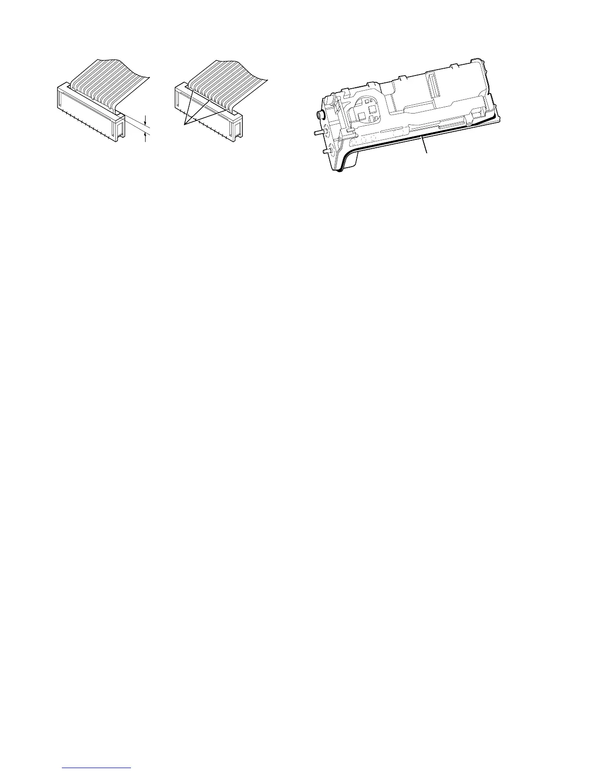
6. Front Cover Assembly to Chassis
a. Install the contoured O-ring/antenna bushing
seal around the antenna and in the groove
provided (see Figure 40-15).
b. Orient the front cover assembly with the chas-
sis, and insert the front cover/display flex
connector into the locking connector of the con-
troller board (refer back to Figure 40-6). Secure
the connection. View the flex connection at a
slight angle from the top of the radio and
ensure that the flex connector is fully seated
into the locking connector as described in
step 4c.
c. Check to make sure that the O-ring is in place,
and slide the chassis (switch end first) into the
front cover assembly. Check to ensure that the
orange emergency button seal slides into posi-
tion freely.
NOTE
When performing the next part of this step, pay
particular attention to the O-ring near the bottom
of the radio to ensure that it does not raise up
and get pinched between the front cover clip and
the chassis.With the top of the chassis fully seat-
ed, lower the bottom of the chassis and press it
into the front cover assembly until it snaps into
place.
d. Check the emergency button again. If it
is cocked to one side, repositioning it may be
necessary.
6. Reinstall the switch knobs and antenna; the shorter
knob with the volume on/off switch, the taller knob
with the channel selector switch.
7. Reinstall the battery.
22
Figure 40-14.

 Loading...


