19
a. Use a small, thin, flat-blade screwdriver (or like
instrument) to help raise the sliding portion of
the connector approximately 1/8 of an inch from
its seated position. A slight prying action, alter-
nating back and forth on the top corners of the
connector, achieves the best results for unlock-
ing the connector.
b. Remove the flex from the chassis connector.
7. Remove the contoured O-ring/antenna bushing seal
from the chassis.
8. Disconnect the controls flex from the connector on
the controller board by following the procedure in
step 6a and 6b.
NOTE
A large portion of the controls flex is attached to the
large metal shield (front shield) with adhesive. Do not
remove the controls flex from the front shield unless
it is absolutely necessary.
9. As a unit, separate the control top, the front shield,
and the controls flex from the chassis and circuit
boards (see Figure 40-8).
NOTE
Four large tabs secure the front shield to the chassis
and hold the RF board and the controller board in the
chassis.
a. Loosen the front shield by prying each of the
four tabs away from the chassis. Be careful not
to pry the tabs any more than is necessary to
free them from their respective retaining slots.
To completely loosen the shield from the chas-
sis, a slight lifting and clockwise twisting action
may be required.
b. Insert a small, flat-blade screwdriver in the
recessed area of the control top and pry the
control top slightly away from the chassis.
c. Completely remove the control top/front
shield/controls flex unit from the chassis.
10. Carefully remove the RF board and the controller
board from the chassis.
NOTE
The RF board and the controller board are connected
together with a jumper flex. The connection is made
more rigid using a hard plastic cover that snaps
across the top of the jumper flex (see Figure 40-9).
C. Disassembly of Control Top
1. Remove the rubber controls seal from the control
top.
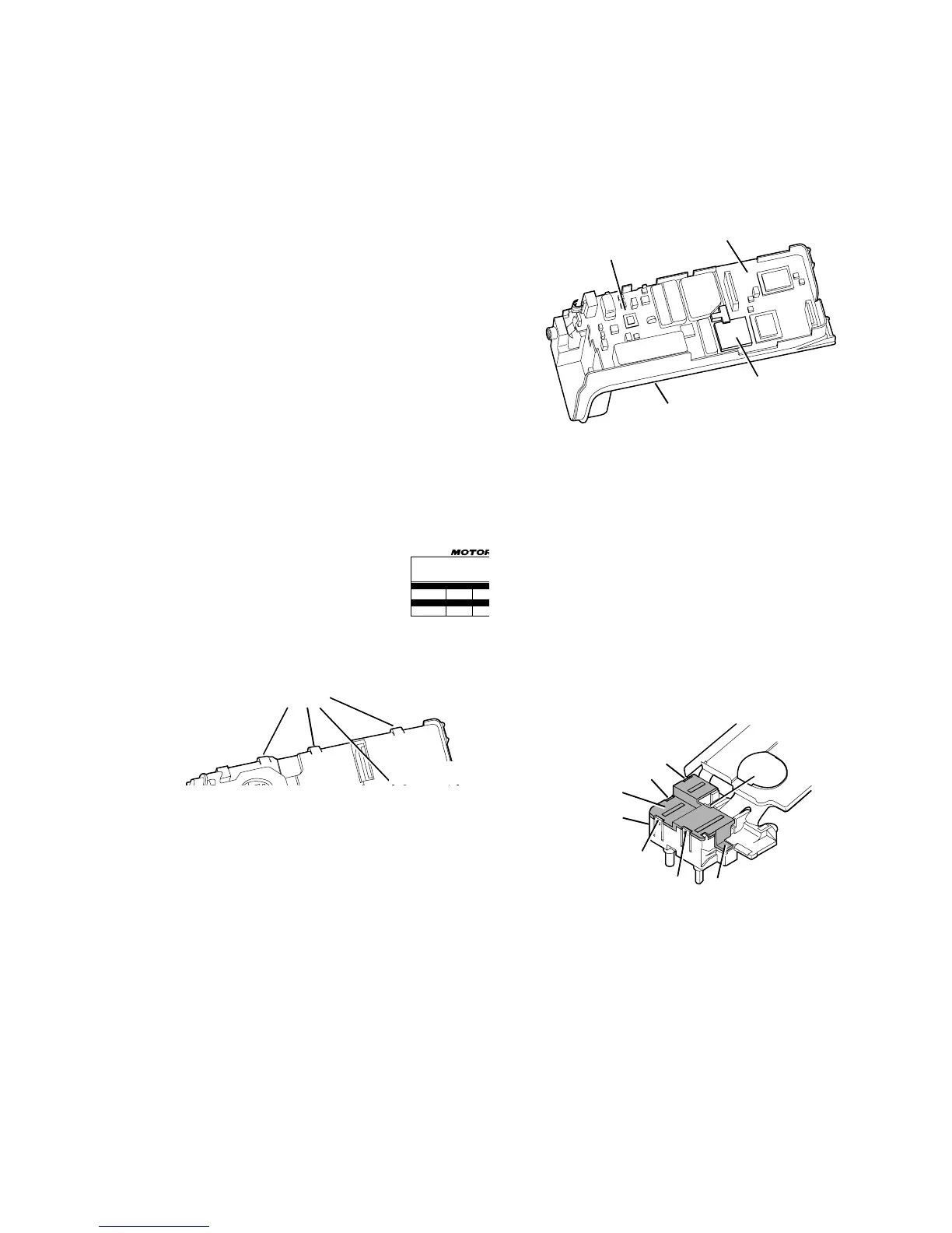
2. Turn the control top such that the black switch hous-
ing cover is facing up.
a. Five retaining clips hold the switch housing
cover to the switch housing. Clips 1, 2,
and 3 are important during disassembly (see
Figure 40-10).
NOTE
To perform step 2b, two tools will be required;
your thumbnail or small, flat-blade screwdriver,
and a pen, pencil, or another small, flat-blade
screwdriver.
b. Using your thumbnail or small, flat-blade screw-
driver, lift the tab that covers the base of the
LED approximately 1/16 of an inch from its
seated position. While applying constant lifting
pressure there, (in order) release clips 1, 2, and
3 with the other tool.

 Loading...


