51
NOTE
The Secure Module is NOT serviceable. The informa-
tion contained in this appendix is only meant to help
determine whether a problem is due to the Secure
Module or the radio itself.
I. INTRODUCTION
The Secure Module is designed to digitally encrypt
and decrypt voice data in Motorola’s MTS 2000 Series
Handie-Talkie™ Portable Radios. The Secure Module
uses a custom encryption integrated circuit (IC) and
an encryption key variable to perform its
encode/decode function. The encryption key variable
is loaded into the Secure Module via the radio’s uni-
versal (side) connector from a hand held key variable
loader. The encryption IC corresponds to the particular
encryption algorithm purchased. The encryption algo-
rithms and their corresponding kit numbers are:
• Data Encryption Standard (DES) NTN7279A
• DES-XL NTN7280A
• Digital Voice Protection (DVP) NTN7281A
• DVP-XL NTN7282A
• DVI-XL NTN7283A
II. CIRCUIT DESCRIPTION
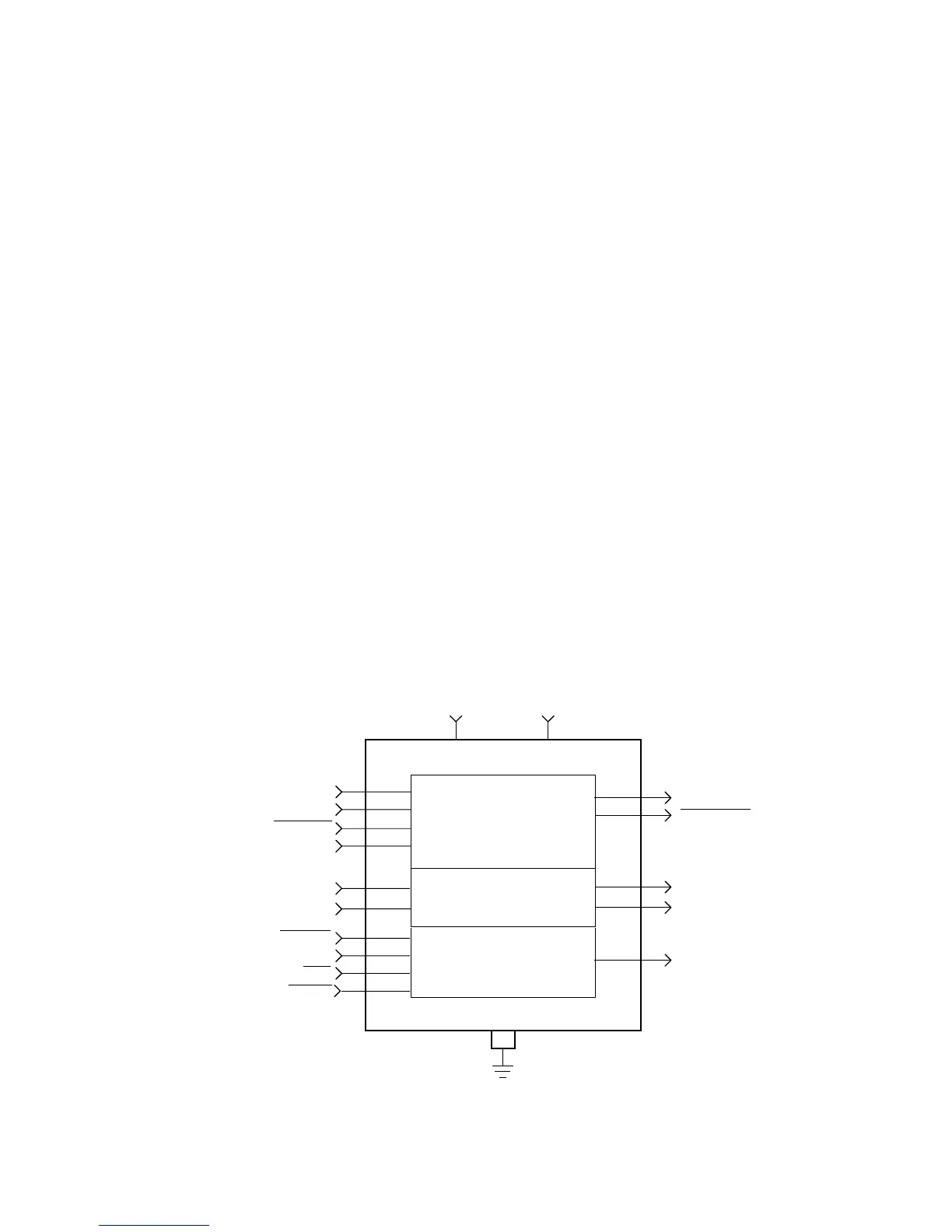
The Secure Module, shown in Figure 1, operates
from two power supplies. The first 5 volt supply (Vdd)
is received from the controller board through connec-
tor plug P1 pin 2. This Vdd supply is turned on and off
with the radio on/off switch. The second supply
(UNSW B+) is received from the controller board
through connector Plug P1 pin 1. UNSW B+ provides
power to the Secure Module as long as the radio bat-
tery is in place.
Key variables are loaded into the Secure Module
through connector P1 pins 13, 15, and 16. One key
variable can be stored in the module at a time. The
key variable is stored in volatile electronic memory, so
it can only remain in memory as long as the radio is
connected to a charged battery. If the battery is
removed or if the battery fails, then a capacitor will
allow the module to retain the key variable for at least
30 seconds while the battery is being replaced.
The radio’s host processor communicates with the
Secure Module on the Serial Peripheral Interface (SPI)
bus. The host processor is the master on this bus,
while the Secure Module is a slave on the bus. The
SPI bus consists of five signal lines. Refer to Table 1
for the signal information. A communications failure
between the host processor and the Secure Module
will be indicated as an “ERROR 09/10” message on
the radio display.
APPENDIX
Secure Modules: NTN7279A, NTN7280A, NTN7281A, NTN7282A, and NTN7283A
for MTS 2000 Radios
Figure 1. MTS 2000 Single Key Secure Module Block Diagram

 Loading...


