Do you have a question about the Motorola L6 and is the answer not in the manual?
Step-by-step guide to remove and replace the phone's battery cover.
Instructions for safely removing and installing the Lithium-Ion battery pack.
Procedure for unlocking, removing, and reinserting the SIM card.
Steps to remove and replace the antenna cover and the antenna assembly.
Guide to remove and replace the metal shield protecting the transceiver PC board.
Instructions for removing and replacing the motor/vibrator assembly.
Steps for disconnecting flex cables, speaker, and coaxial cable from the PC board.
Procedure for disconnecting and removing the camera module flex connector.
Steps to release housing catches and detach the front housing assembly.
Instructions for removing the keypad PC board and its connectors.
Steps to lift and remove the keypad from the front housing.
Guide to release latches and remove the display module assembly.
| Display Size | 1.8 inches |
|---|---|
| Resolution | 128 x 160 pixels |
| Internal Storage | 10 MB |
| Main Camera | VGA |
| Dimensions | 113 x 49 x 10.9 mm (4.45 x 1.93 x 0.43 in) |
| Weight | 86 g (3.03 oz) |
| Network Technology | GSM |
| 2G bands | GSM 850 / 900 / 1800 / 1900 |
| GPRS | Class 10 |
| EDGE | Class 10 |
| Announced | 2005, Q4 |
| Status | Discontinued |
| SIM | Mini-SIM |
| Memory Card slot | No |
| Phonebook | 1000 entries |
| Video | Yes |
| Alert types | Vibration; Downloadable polyphonic, MP3 ringtones |
| Loudspeaker | Yes |
| 3.5mm jack | No |
| WLAN | No |
| Radio | No |
| Browser | WAP 2.0/xHTML |
| Games | Yes + downloadable |
| Java | Yes, MIDP 2.0 |
| Bluetooth | v1.2 |
| Messaging | SMS, EMS, MMS |
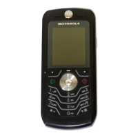
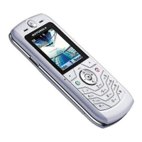
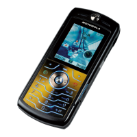
| Colors | Black, Silver, Pink, Blue |
| OS | Proprietary |