EasyManuals Logo

Motorola L6 User Manual

Motorola L6
54 pages
To Next Page IconTo Next Page
To Previous Page IconTo Previous Page
Page #24 background imageLoading...
Page #24 background image
24 October 14, 2005 6809495A75-O
Disassembly L6
Removing and Replacing the Transceiver PC Board
1. Remove the battery cover, battery, SIM, and rear housing as described in the
procedures..
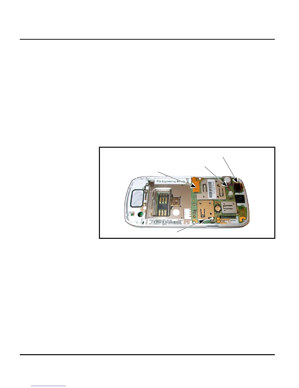
2. Insert the flat end of the disassembly tool under the flex connector to unseat
it from the transceiver PC board (see Figure 12).
3. Use the metal tweezers to unseat the alert speaker connector from it’s socket
on the transceiver PC board (see Figure 12).
4. Use the disassembly tool to unseat the flex connector from its socket on the
Transceiver PC board (see Figure 12).
G
This product contains static-sensitive devices. Use anti-static handling procedures
to prevent ESD and component damage.
G
The flexible printed cable (FPC) (flex) is easily damaged. Exercise extreme care when
handling.
050783o
Figure 12. Removing the Transceiver PC Board Connectors
Flex Connector
Alert Speaker Cable
Coaxial Cable
Display Flex Connector

Other manuals for Motorola L6

Questions and Answers:

Question and Answer IconNeed help?

Do you have a question about the Motorola L6 and is the answer not in the manual?

Motorola L6 Specifications

General IconGeneral
Display Size1.8 inches
Resolution128 x 160 pixels
Internal Storage10 MB
Main CameraVGA
Dimensions113 x 49 x 10.9 mm (4.45 x 1.93 x 0.43 in)
Weight86 g (3.03 oz)
Network TechnologyGSM
2G bandsGSM 850 / 900 / 1800 / 1900
GPRSClass 10
EDGEClass 10
Announced2005, Q4
StatusDiscontinued
SIMMini-SIM
Memory Card slotNo
Phonebook1000 entries
VideoYes
Alert typesVibration; Downloadable polyphonic, MP3 ringtones
LoudspeakerYes
3.5mm jackNo
WLANNo
RadioNo
BrowserWAP 2.0/xHTML
GamesYes + downloadable
JavaYes, MIDP 2.0
Bluetoothv1.2
MessagingSMS, EMS, MMS
ColorsBlack, Silver, Pink, Blue
OSProprietary

Related product manuals