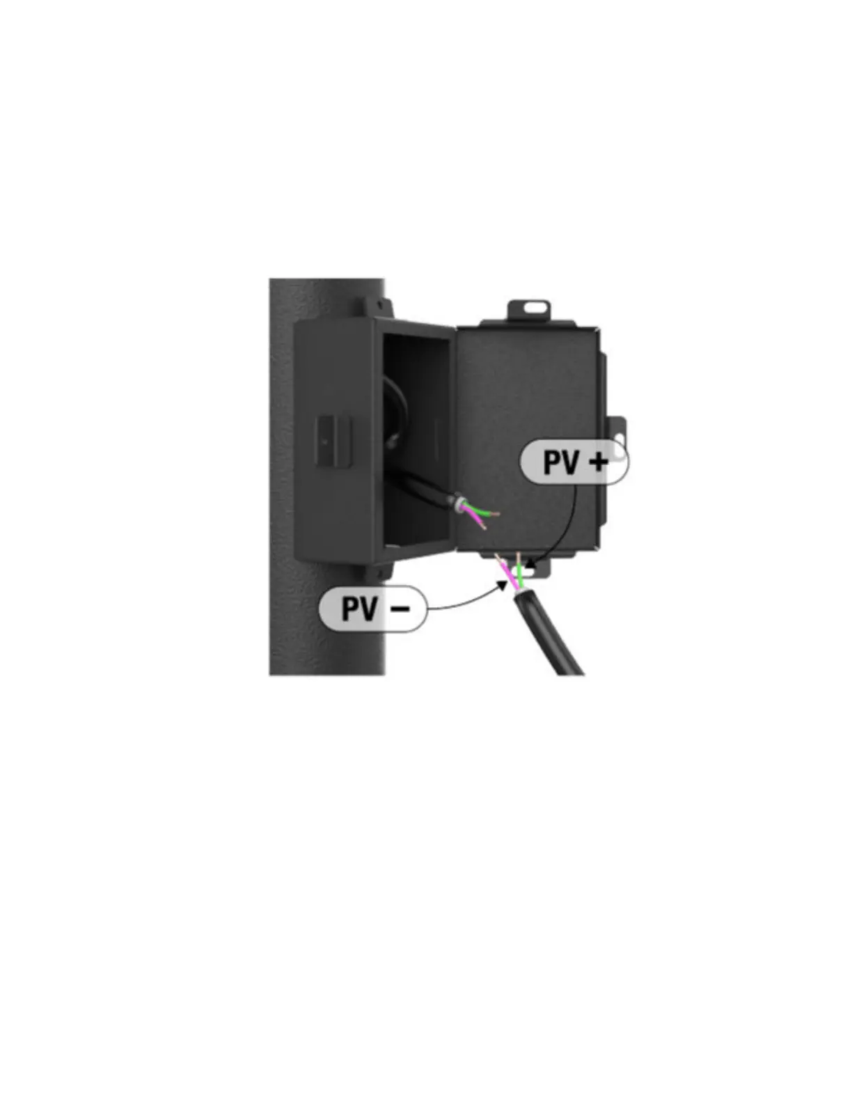
Strip off one-half to one inch of insulation as necessary.
b. Optional: Slip a section of Wire Shrink Wrap over each conductor.
c. Use solder, wire twisting caps, or securely twist to splice the conductors.
Splice the positive (PV+) DC power cable conductor to the positive (PV+) power source conductor.
Splice the negative (PV-) DC power cable conductor to the negative (PV-) power source
conductor.
d. Securely insulate the splices with the Wire Shrink Wrap or Electrical Tape.
Figure 14: Conductors Connection
2. Check the power cable length.
a. Run the DC Power Cable to the approximate location of the camera.
b. Use a Zip-Tie to secure the end of the cable in place.
3. Go to Camera Installation.
3.6
Camera Installation
The camera can be mounted to a pole with the Metal Band Straps, or to a surface with the Lag Bolts. Before
installation, the internal camera batteries must be fully charged.
MN010089A01-AD
Chapter 3: Hardware Installation
53