3-10 Bench Setup
SG 2000 Installation and Operation Manual
Analog Return Path
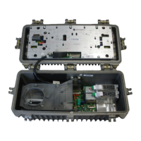
Figure 3-1 illustrates the location of the return-path transmitter modules.
To set up analog return-path transmitters:
1 Confirm the transmitter configuration required. For a single transmitter, use the optical
transmitter A position. The redundant transmitter uses the optical transmitter B position.
Redundancy options are discussed in Section 5, “Operation.”
2 For each return-path transmitter, measure the optical power level at the test point provided on the
top panel of the transmitter as illustrated in Figure 5-12. The scaled voltage present at this test
point is 1.0 V/mW.
3 Verify that the green LED (ON), located on the top panel of the transmitter, is illuminated to
confirm enable status. Refer to Section 5, “Operation,” for
FAULT LED functions.
4 Review return-path system levels. The unit is configured to drive the laser to the recommended
level (+15 dBmV) when the total combined power at all ports is approximately +28 dBmV.
Digital Return Path
To set up digital return-path transmitters:
1 Confirm the transmitter configuration required. For a single transmitter, use the optical
transmitter A position. The redundant transmitter uses the optical transmitter B position.
Redundancy options are discussed in Section 5, “Operation.”
2 Verify that the green LED (ON), located on the top panel of the transmitter, is illuminated. Refer
to Section 5, “Operation,” for
FAULT LED functions.
3 Review return-path system levels. The unit is configured to drive the laser to the recommended
level (+15 dBmV) when the total combined power at all ports is approximately +28 dBmV.
Two models of return path modules are available with analog and digital transmitters:
T With the SG 2000 return path module/combined (SG2-RPM/C), the total combined power at
all four ports totals approximately +28 dBmV.
T With the SG 2000 return path module/split (SG2-RPM/S), the total combined power at each
pair of ports is approximately +28 dBmV.
For more specific information regarding return path setup procedures, refer to the supplemental
document Return Path Level Selection, Setup, and Alignment Procedure.

 Loading...