Bench Setup 3-21
SG 2000 Installation and Operation Manual
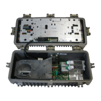
Figure 3-15 illustrates a complete SG2 lid with the DS-SG2-DRRB board (shaded gray) installed:
Figure 3-15
SG2 lid configured with the DS-SG2-DRRB board
INPUT
A
INPUT
B
STATUS DS-SG2-DRT-2X/A
1310 DFB
RF
INPUT
B
SG2000
Digital Transmitter
DANGER
INPUT
A
INPUT
B
STATUS DS-SG2-DRT-2X/A
1310 DFB
RF
INPUT
B
SG2000
Digital Transmitter
DANGER
J1
J2
DS-SG2-DRRB board
When signals are applied to port in and port 1, they are routed directly to the transmitters through the
D-type connectors on the lid board.
When signals are fed from port out and port 3, they are routed to the transmitters from the cables on
the DS-SG2-DRRB-SR board.

 Loading...