Bench Setup 3-19
SG 2000 Installation and Operation Manual
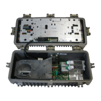
Figure 3-13
DS-SG2-DRRB board installed
SG2-DRT-2X/A
(”B” location)
SG2-DRT-2X/A
(”A” location)
DS-SG2-DRRB board
Push handle
Push handle
4 Insert the MCX connector terminating cable J1 into RF INPUT B on DS-SG2-DRT-2X/A in the
transmitter A location.
5 Insert the MCX connector terminating cable J2 into RF INPUT B on DS-SG2-DRT-2X/A in the
transmitter B location.
6 Remove the existing 0 dB jumpers and install 1 dB JXPs in the four return-path JXP locations on
the E-pack as illustrated in Figure 3-14.

 Loading...