5-6 Operation
SG 2000 Installation and Operation Manual
For upgrading to split return operation, with DS-SG2-DRT-2X/A transmitters installed in positions
A and B, the SG2-RPM/C board must be replaced with an SG2-RPM/S board. The main RF chassis
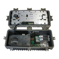
must be removed to perform this exchange. Figure 5-9 illustrates the inside bottom view of the RF
chassis, the location of the SG2-RPM/C board, and the removal sequence:
Figure 5-9
RF chassis and location of the SG2-RPM/C or SG2-RPM/S board
Cover
SG2-RPM/C
Power connector
RF chassis
1 Remove any fuses at F1, F2, F3, F5, or F6 to prevent arcing of the housing connectors.
2 Remove the six 5/16-inch hex-head screws that secure the RF chassis to the housing. Remove
the housing.
3 Remove the six ¼-inch hex-head screws that secure the rear cover. Remove the cover.

 Loading...