6 Wiring of the Device
30 Rev. 08/2018
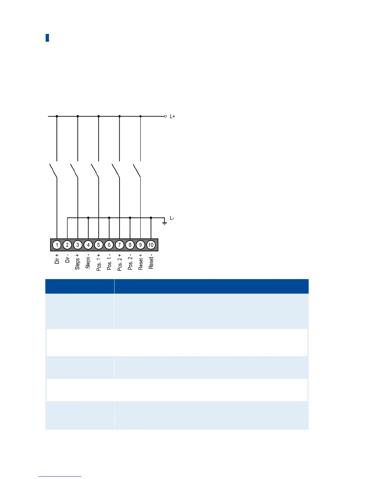
6.3 Wiring Binary Inputs
The binary inputs are wired using the 10-pole plug. The inputs can be switched both on the side
of the operating voltage and on the ground side.
L ≙ 5 V DC to 32 V DC
Pin Designation Function
1 Dir + The level at the binary input indicates whether the openings of the
gas supply of the gas mixer or the throttle move in the open or
closed direction when pulses occur at the input Steps (see
Inputs/Outputs – Control Setup on page 56).
2 Dir -
3 Steps + Pulses on the input modify the openings for the gas supply of the
gas mixer or the throttle step by step (see Inputs/Outputs – Control
Setup on page 56).
4 Steps -
5 Pos. 1 + If a high level is applied, position 1 as defined in the configuration
is approached.
6 Pos. 1 -
7 Pos. 2 + If a high level is applied, position 2 as defined in the configuration
is approached.
8 Pos. 2 -
9 Reset + If a high level is applied for at least 50 ms, the device exits the error
mode and the stepper motor driver is reset. Subsequently, it
initiates a reference run.
10 Reset -


 To Next Page