6 Wiring of the Device
34 Rev. 08/2018
CAN bus wiring
Note the following when connecting the CAN bus:
– Each bus end must be fitted with a terminating resistor of 120 Ω (see
drawing).
– The maximum wire length depends on the bit rate:
Bit rate Maximum wire
length
Maximum length
of a stub
Maximum length
of all stubs
1 Mbit/s 25 m (82') 1.5 m (5') 7.5 m (25')
800 kbit/s 50 m (164') 2.5 m (8') 12.5 m (41')
500 kbit/s 100 m (328') 5.5 m (18') 27.5 m (90')
250 kbit/s 250 m (820') 11 m (36') 55 m (180')
125 kbit/s 500 m (1,640') 22 m (72') 110 m (360')
50 kbit/s 1,000 m (3,280') 55 m (180') 275 m (902')
– Only use cables that are specified by the manufacturer for CAN bus.
6.7 Wiring Modbus
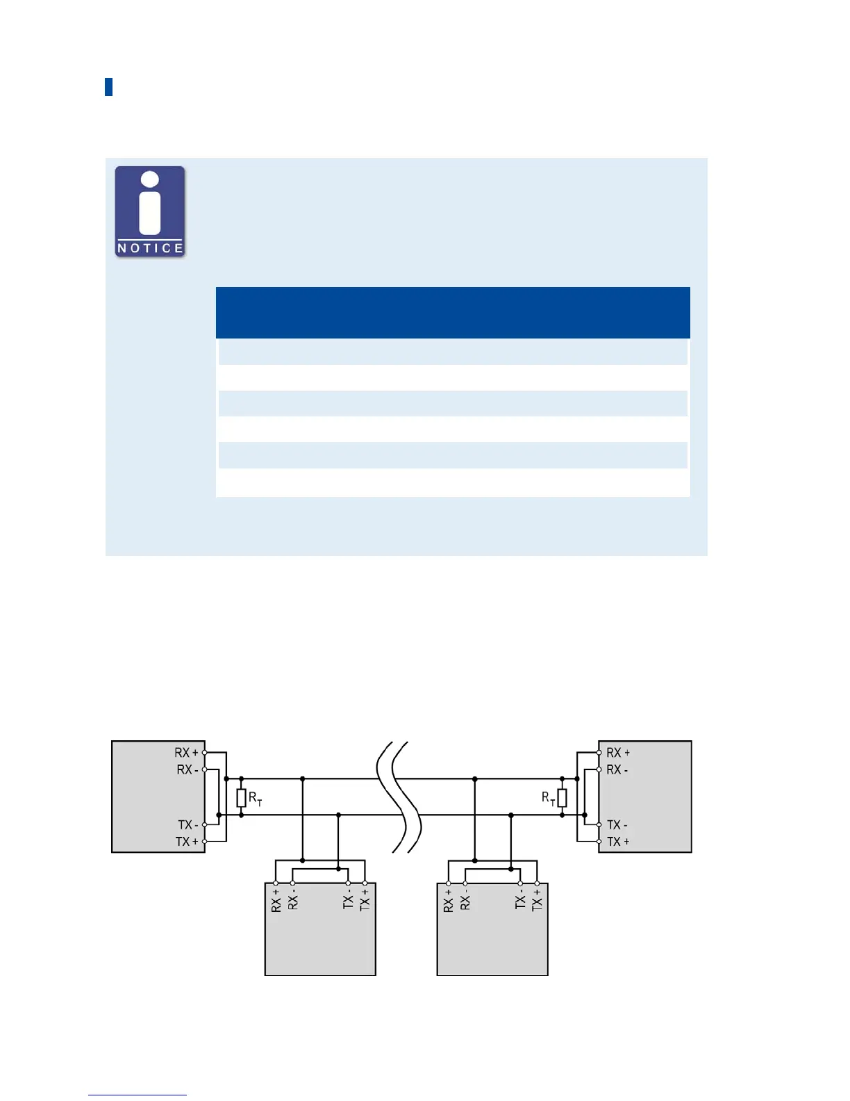
The Modbus can be wired as half duplex or full duplex, and twisted cables must be used. With
both variants the load resistance RT is the characteristic impedance of the cable.
Wiring Half Duplex
First device Last device
Second device Second-to-last device


 To Next Page