6 Wiring of the Device
32 Rev. 08/2018
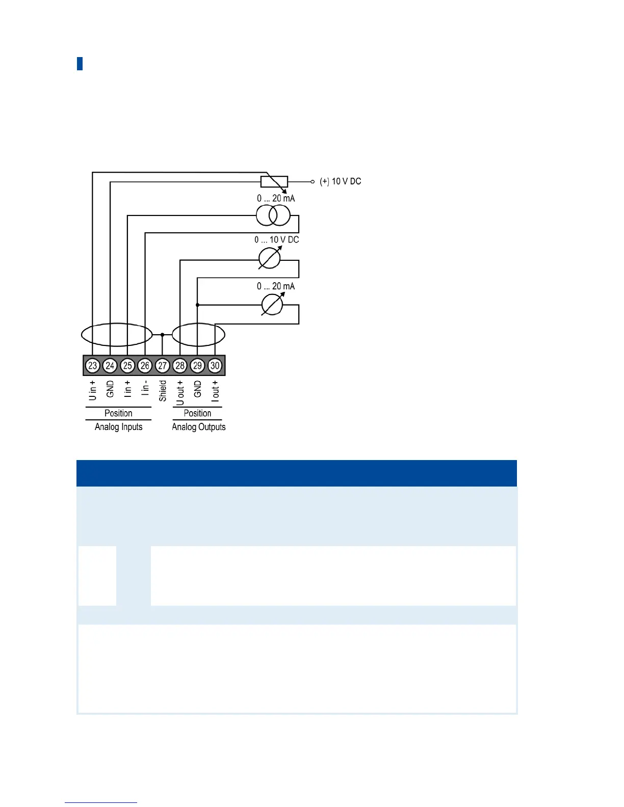
6.5 Wiring Analog Inputs and Outputs
The analog inputs and outputs are wired via an 8-pin connector and are therefore not compatible
with the corresponding 14-pin connector of the VariStep stepper motor driver.
Pin Designation Function
23
Analog Inputs
Position U in + Voltage input for adjustment of the openings for the
gas supply of the gas mixer or the throttle (see
Inputs/Outputs – Control Setup on page 56). The input
has a value range from 0 V to 10 V.
24 Position GND
25 Position I in + Current input for adjustment of the openings for the
gas supply of the gas mixer or the throttle (see
Inputs/Outputs – Control Setup on page 56. The input
has a value range from 0 mA to 20 mA.
26 Position I in -
27 Shield Shield
28
Analog Outputs
Position U out + Voltage and current output with shared ground. The
outputs export the current position of the stepper
motor as appropriate signal. They have a value range
from 0 V to 10 V and from 0 mA to 20 mA
29 Position GND
30 Position I out +
 Loading...