7 Operation
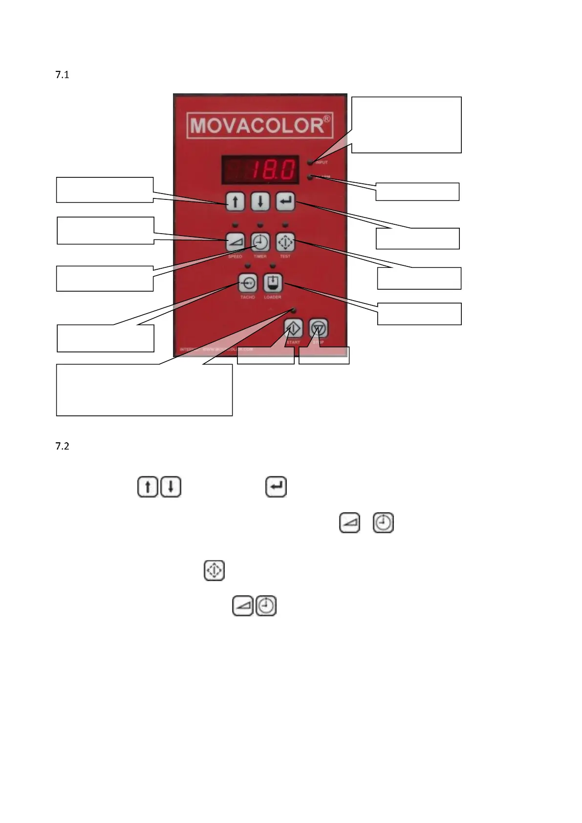
The Interface
General
Connect motor before switching on the controller
All changes have to be entered to acknowledge.
A blinking value means the changed data is not entered.
To cancel a changed value, press the specific function button ( or ) again.
Most functions have a designated key and a LED on the interface. When a function is activated the LED of
that key/function will light up.
All functions except the test function can be activated when the unit is started.
(depending on the chosen configuration.)
Only one of the following functions , , can be active at the same time. This means no other function
can be activated before the active function is deactivated
The unit can be set to different configurations, see paragraph 7.3 and 7.4