UC-8410A HW UM Hardware Connection Description
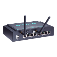
4. Find the three cable connectors below the module. Note that G is for the GPS antenna, and N (in the middle)
is for the cellular antenna.
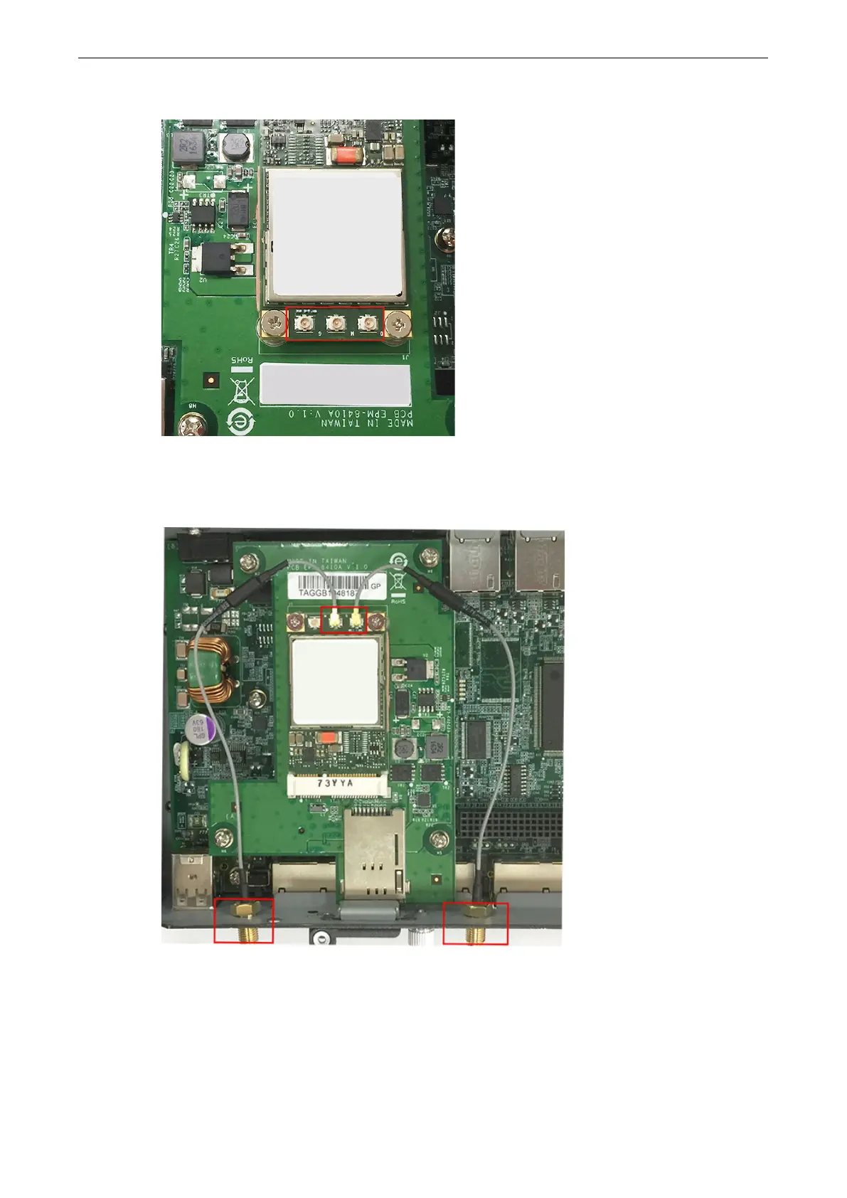
5. Attach one end of the cellular antenna cable to the connector marked N and connect the other end of the
cable to the W1 apperture on the front panel of the computer.
Use the same method to connect the GPS cable and its connector to the W2 apperture on the front panel of
the computer. Remove the black antenna hole protection cover before you do so.
6. Pass the antenna mount’s threaded connection ring through the mounting hole while keeping the locking
washer against the front panel.