mr
.
steam
®
steamtherapy
®
Installation, Operation & Maintenance Manual
_____________________________________________________________________
installer
5
MS SUPER 4E, 5E, 6E TYPICAL CONFIGURATION
Installation Instructions for Models:
MS-Super 4E, MS-Super 5E and MS-Super 6E
1.
Install each steam generator as in a single installation.
Install generators as close as practical to each other,
not exceeding 12 feet. The interconnecting cable length
is 12 feet.
2. IMPORTANT NOTE:
Power must be disconnected at the
main electrical supply. Remove steam generator covers.
Retain screws and covers for reuse.
3.
Connect the eTEMPO/PLUS
®
control to either unit per
instructions on pages 17-22.
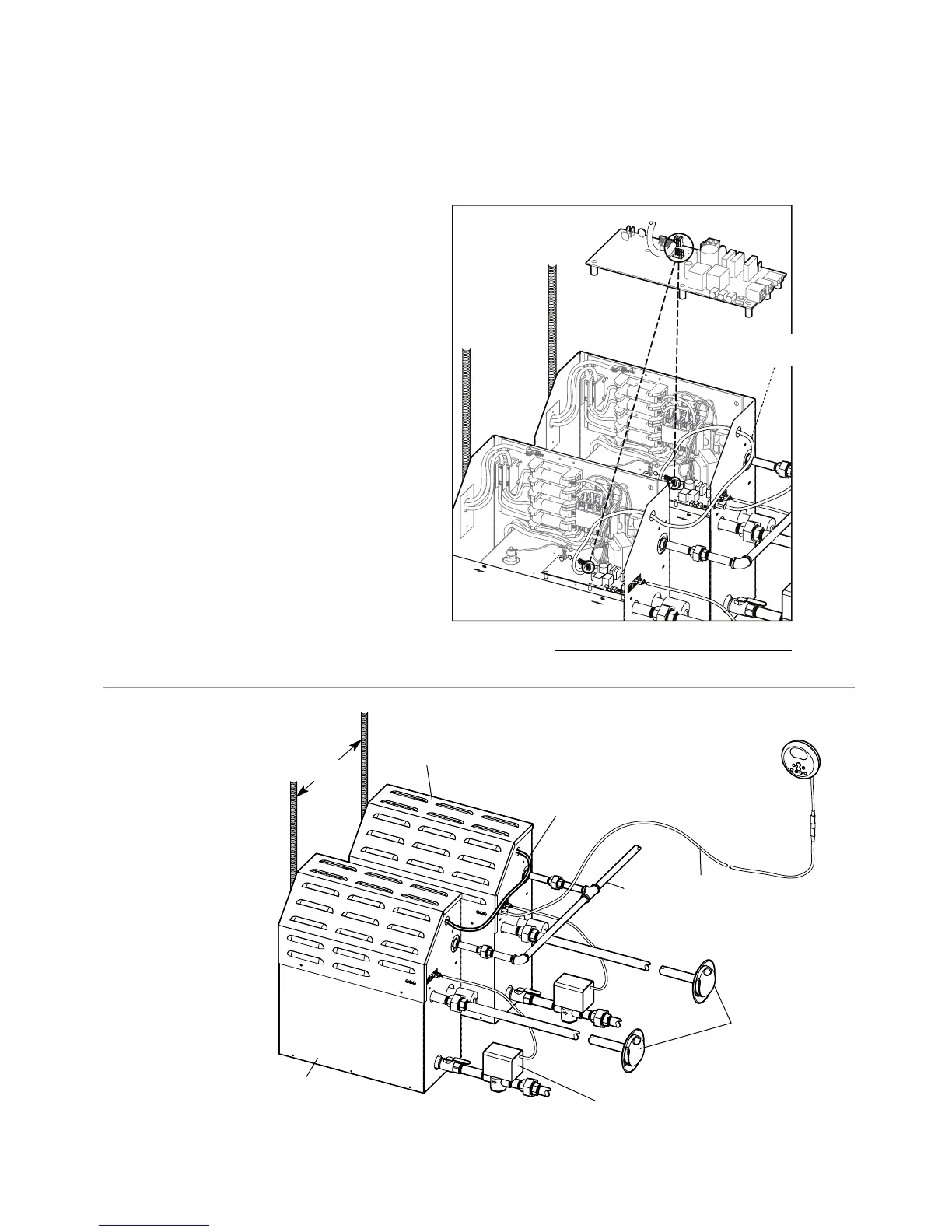
4.
Remove one knock-out on each generator as shown.
Insert the ends of interconnecting cable provided
(PN 103904) through the knock-outs as shown in
Diagram A. Connect each end to the printed circuit
board connector labeled "TANDEM" as shown.
5.
Prevent the interconnecting cable from contacting hot
surfaces such as steam outlet, safety valve and the like.
6.
Connect separate plumbing and power supplies for
each unit. Replace covers with cover screws.
NOTE:
The secondary unit will de-energize when the steam
room reaches steambathing temperature resulting in a
more gentle and energy efficient operation.
Diagram A
P
rinted Circuit Board Component
s
hown enlarged for illustrative purpose.
Interconnecting
Cable PN: 103904
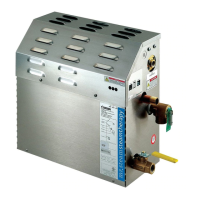
NOTE: FOR ILLUSTRATIVE PURPOSES ONLY.
Diagram B
MS Super 4E, 5E, 6E
Typical Installation
shown with Optional
AutoFlush
Provide unions as required
to facilitate installation and
disconnection of piping
Primary Unit
Interconnecting
Cable
Control
Cable
Secondary Unit
eTEMPO/PLUS
®
Control
Optional AutoFlush
®
, see
AutoFlush
®
Installation page 13
Steam Heads
shown with optional
acrylic shields
NOTE: For illustrative purposes only. Consult with qualified designer,
architect or contractor for steam room construction details.
Water
Feed
Line
Power
Supply