Bolt™ Jr+ Quick Start Guide
34
Bolt™ Jr+ Quick Start GuideBolt™ Jr+Quick Start Guide
Appendix 1 Bolt™ Jr+ panels
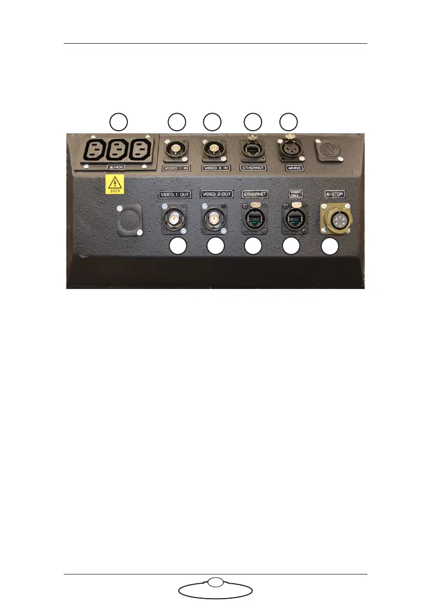
Bolt™ Jr+ Track Base panel connector summary
1. 240V AC output, for general use by additional devices that you want
to mount on the base.
2. VIDEO 1 IN input connector for the video 1 signal from the camera.
This has a straight-through internal connection to the VIDEO 1
OUT connector (6).
3. VIDEO 2 IN connector for the video 2 signal from the camera. This
has a straight-through connection to the VIDEO 2 OUT connector
(7).
4, 8. ETHERNET connectors for communications between multiple
Ethernet devices on the rig. These two connectors share a common
Ethernet hub within the Bolt Jr+ Base. You ordinarily attach one of
these to the computer stack (via the umbilical cable) and one to
Ethernet connector on the base of the arm to service the Ulti-box
mounted on the arm.
5. 48V OUT power connector. You usually use this to power the
Ulti-box (and its attachments) on the Bolt Jr+ arm.
4321 5
876 9
10