15
RT-14 Quick Star t GuideRT-14Quick Start Guide
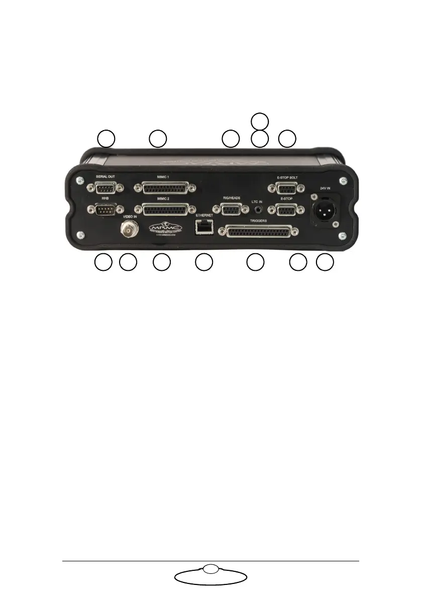
Appendix 3 Rear panel
Panel and connector summary
1. SERIAL OUT connector is connected to the rig or head that are
loaded and run over SERIAL. For pin-out information see Serial Out
connector on page 17.
2. HHB connector to the D-type connector on the Hand Held box
marked HHB. The Hand Held Box (HHB) allows the user to
remotely move the camera, for example to the exact desired position
for setting up a move. For pin-out information see HHB connector
on page 17.
3, 4. MIMIC 1 and MIMIC 2 connectors are used if different controllers
such as Pan bars, Focus, and Zoom controllers are being used in the
system. Flair motion control software must then be configured to
accept the correct controller on the correct MIMIC input. For
pin-out information see MIMIC 1 connector on page 18 and MIMIC
2 connector on page 19.
5. VIDEO IN connector for synchronisation signal from the
camera.The RT-14 accepts and external video source, which is
decoded to provide a frame sync pulse which sent to Flair for it to
match the camera video frame rate and phase. This uses a standard
coaxial cable. For pin-out information see Video In connector on
page 20.