ENGLISH
MSC Pro-Source Man. cod. B411107FG 11
SETUP
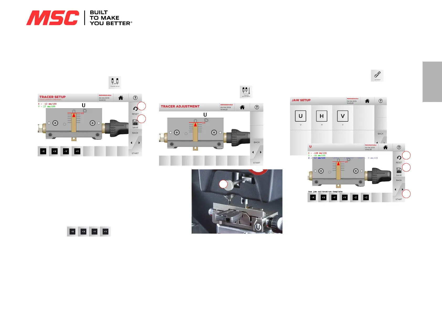
5.3.1 Tracer Setup
To calibrate the tracer, proceed as follows:
•From the CALIBRATIONS MENU, select:
1. Insert the template in the clamp, bringing it flush against it as
shown in picture A.
2. To calibrate the tracer automatically, just press START from
this page.
3. Save your changes by pressing “1”.
Note: If you leave the page without pressing the "1" key, all
changes shall be lost.
4. To reset the changes and go back to the previous setting,
press “2”.
5. If necessary, correct the position of the X-Y axes with the fol-
lowing keys:
6. The change in elevation will be shown in the top left corner of
the screen.
5.3.2 Tracer Adjustment
For the decoding of car keys (laser or edge cut) the tracer must be
set at a specific height.
How to proceed:
•From the CALIBRATIONS MENU, select:
• Insert the template in the clamp, bringing it flush against it as
shown in picture A and press START
• The software will request that the tracer be lifted completely
using the adjustment knob (1).
• Then the unit will position the tracer above the template and
the system will ask to lower it, again using the adjustment
knob (1), and place it on the template itself.
• Now lock the tracer in place.
5.3.3 Jaw Setup
How to proceed:
•From the CALIBRATIONS MENU, select:
• Install the required jaw and select the corresponding code
from the JAW SETUP menu.
• Place the template flush on the clamp as shown in picture A.
• Press “START” and follow the instructions on screen to cali-
brate the clamp correctly.
• The elevation will be shown in the top left corner of the
screen.
•Save your changes by pressing “1”.
Note: If you leave the page without pressing the "1" key, all
changes shall be lost.
• To reset the changes and go back to the previous setting,
press “2”.
Note: For all other supplied or optional clamps, select the de-
sired clamp to be calibrated and follow the procedure
displayed in the console, similar to the one described in
this paragraph.