English
User manual
15
WARNING! The manufacturer is not responsible for any damage or injury to human health
resulting from non-compliance with the requirements of this user manual.
5.1. Safety guidelines
1. The test bench shall be operated by the workers qualified to work with certain types of
equipment and received appropriate training in the safe operation.
2. In case of a power outage, the test bench shutdown is mandatory when cleaning and lubricating
the bench and in emergencies.
4. To ensure electrical and fire safety PROHIBITED:
- connect the bench to the electrical network having faulty protection against current overloads
or not having such protection;
— use a socket without a grounding contact to connect the bench;
— use extension cords to connect the bench to the electrical network. If the socket is far from
the bench installation site, it is necessary to modify the electrical network and install the socket;
- operation of the bench in defective condition;
- Independently to repair and make changes to the design of the bench, because it can lead to
serious damage to the bench and deprive the right to warranty repair;
5. The units with a running drive must not be left unattended on the test bench.
6. While mounting and dismounting of a unit from the bench, to prevent arms from harming, be
more cautious.
7. The diagnosed alternator must be securely fastened.
5.2. Preparing the bench for operation
The bench is supplied packed. Once unpacked, it should be inspected to make sure it has no
damages. If the damages were revealed, prior to the equipment starting, contact the manufacturer
or a dealer.
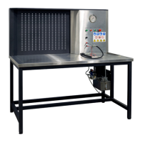
The bench is installed on a flat floor, if necessary to compensate for unevenness of the surface,
you can adjust the bench legs in height. When installing the stand, ensure a minimum clearance
of 0.5m from the right side of the stand for free air circulation.
Prior to the bench operation, connect:
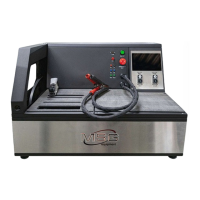
- the battery 12V to the terminals Battery 1 in the battery section (ref. 5, fig. 1). For the diagnostics
of the alternator/starter 24V, connect the second battery to the terminals Battery 2;
- electric mains 400V.
WARNING! For the diagnostics of the voltage regulators 24V, only one battery can be
connected to the terminals Battery 1.