English
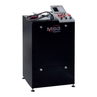
Test bench MS002 COM
20
6.4. Diagnostics of voltage regulator
Referring to OEM of voltage regulator, find the information about the terminal references on the
Internet. In addition, you can refer to the Appendix 3 where the most common voltage regulator
connections are specified. Referring to the voltage regulator connector terminals and the
Appendix 1, identify its type.
WARNING! The diagnostics mode shall conform with the diagnosed voltage regulator type.
6.4.1. Lamp voltage regulator diagnostics
1. Connect voltage regulator with the bench diagnostic outputs, except B+ output.
2. Turn on the mode of the diagnostics of voltage regulators pressing the button Voltage regulator
tester. To test the lamp regulators, you shall not choose any mode because the control lamp D+
works at any mode.
3. Choose the nominated voltage of the diagnosed voltage regulator pressing the button either
12V or 24V.
4. Connect the bench diagnostic output B+ with the corresponding voltage regulator terminal.
Now, the stabilization voltage rate shall be within 14 - 14.8 V for 12V voltage regulators, within 28
-29.8 V for 24V voltage regulators, and it shall conform with the specifications.
5. Disconnect the cable ST from the voltage regulator. The control lamp indicator (ref. 5, fig. 3)
shall light up. Connect ST cable back - the control lamp indicator shall go off.
6. Failure to comply with the one of the paragraphs 4 – 5 indicates the voltage regulator defects.
7. Press Voltage regulator tester button to exit the diagnostics mode. Disconnect the cables from
voltage regulator.
6.4.2. P-D, C, SIG, RLO voltage regulator diagnostics
1. Connect voltage regulator with the bench diagnostic outputs, except B+ output.
2. Turn on the mode of the diagnostics of voltage regulators pressing Voltage regulator tester
button.
3. Choose the nominated voltage of the diagnosed voltage regulator pressing 12V button.
4. Connect the bench diagnostic output B+ with the corresponding voltage regulator terminal.
Here, the stabilization voltage rate shall become equal to the nominated rate with the possible
deviation -0.2V.