English
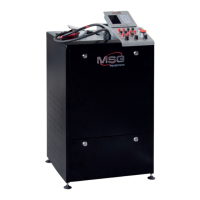
Test bench MS002 COM
10
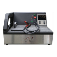
5 – Button «OFF/ON» - turns on/off the bench supply. If the button «EMERGENCY STOP» is
pressed, the button «OFF/ON» is not active.
6 – Indicator of control lamp operation.
7 – Regulators:
REGULATION GC – setting of the alternator output voltage. It’s used when connecting the
alternator to the terminal GC.
ELECTRICAL LOAD – setting of the alternator electric load range (imitates car loads). Press to
smoothly switch off the load down to zero level.
ROTATION SPEED – control of speed and rotation direction of drive. Press to stop the drive.
4.1. Displayed data
The information shown on the display when the following types of alternator/voltage regulator is
diagnosed: Lamp, P-D, C, SIG, RLO (see fig. 4 - 8):
VOLTAGE, DC – rate of generation voltage that is provided by alternator/regulator.
DFM, % – duty ratio of PWM signal received through FR channel (on-condition rate of rotor
winding).
АМР, DC – for alternator - it’s a load; for voltage regulator - the rate of the current that is supplied
to the rotor excitation winding; for starter - the rate of the current that is consumed by starter
electric motor.
АМР, АС – rate of the alternator alternating current output, ripples.
ТАСНОМЕТЕR – drive speed rate.
D – rate of generation voltage that is set by the bench.
Р – rate of the on-condition of rotor winding.