English
User manual
9
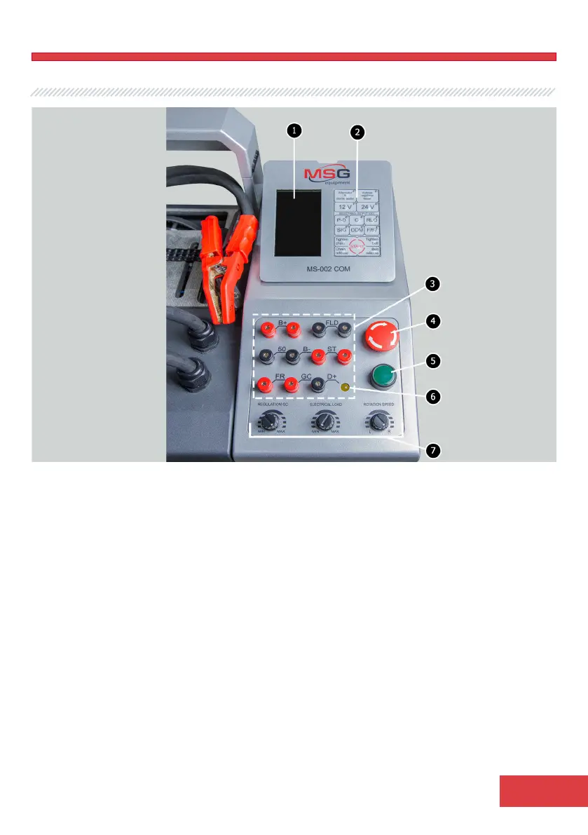
Figure 3. Bench control panel
3 – Diagnostic outputs - for the connection to voltage regulator terminals:
В+ – for connection to terminals: 30, B+, IG, S, AS, BVS, A, 15;
FLD» – outputs - for the connection of the brushes of the voltage regulator at diagnostic mode
of voltage regulator or relevant terminals: DF, F, FLD;
В- – negative (earth, terminal 31);
D+ – input of control lamp of voltage regulator. It’s designed for the connection of the
following voltage regulator terminals: D+, L, IL, 61;
ST – output for the connection to the stator outputs (terminals) of voltage regulator: P, S, STA,
Stator;
GC – output connected to the control terminal of the voltage regulator: COM, SIG, etc.;
FR – alternator load control, connected to: FR, DFM, M;
50 – output connected to the starter terminal 50.
4 – Button «EMERGENCY STOP» - crisis shut down of bench supply.