English
Test bench MS002 COM
8
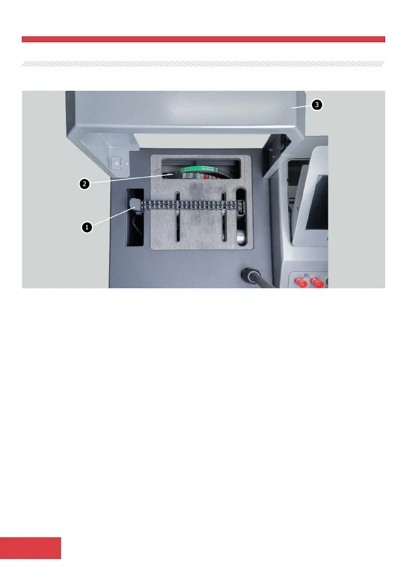
The bench is operated from a working spot (fig.2) that consists of:
Figure 2. Bench working spot
1 – Unit fixing chain.
2 – Alternator drive belts: V-belts and poly V-belts.
3 – Protective housing. When the protective housing is up, the diagnostics will be blocked.
The control panel (fig. 3) consists of the following main elements:
1 – Display – diagnostic data displaying.
2 – Control panel - consists of the following buttons:
Alternator & starter tester – on/off the mode of diagnostics of alternators and starters;
Voltage regulator tester – on/off the mode of diagnostics of voltage regulator;
12V/ 24V – setting the rated voltage of the diagnosed unit;
P-D, С, RLO, SIG, СОМ – setting the type of the diagnosed alternator;
F/67 – mode of diagnostics of alternator that doesn’t have the integral voltage regulator;
Tighten chain/Chain release – control of tightening/loosening of unit fixing chain;
Tighten belt/Belt release – control of tightening/loosening of alternator drive belt;
START – switching on/off the terminal 50 for the starter start.