Chapter 2
2-14
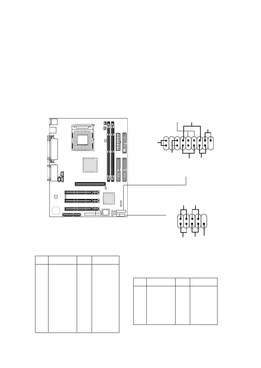
Case Connectors: JFP1 & JFP2
The Keylock (reserved), Power Switch, Reset Switch, Power LED, Speaker,
and HDD LED are all connected to the JFP1 connector block. The other case
connector block JFP2 is compliant to Intel Front Panel I/O Connectivity
Design Guide and can connect to the the Power Switch, Reset Switch, Power
LED and HDD LED on the case.
Pin Description Pin Description
1 Keylock 10 Keylock
2NC 11NC
3 HDD_LED+ 12 HDD_LED-
4 GND 13 CASE_SPK
5 PWR_LED Y 14 CASE_SPK
6 PWR_LED G 15 CASE_SPK
7 PWR_SW+ 16 CASE_SPK
8 PWR_SW- 17 RESET+
9 NC 18 RESET-
JFP1 Pin Definition
Pin Description Pin Description
1 *HDD_LED+ 2 PWR_LED G
3 HDD_LED- 4 PWR_LED Y
5 RESET- 6 PWR_SW+
7 RESET+ 8 PWR_SW-
9 RSVD_DNU 10 NC
JFP2 Pin Definition
* Hard disk LED pullup (330 ohm) to +5V
JFP1
Power
Switch
Power
LED
+
Reset
Switch
HDD
LED
+
Speaker
Buzzer
(short pin)
14
15
Keylock
(Reserved)
Reserved
JFP2
Power
Switch
Power
LED
Reset
Switch
HDD
LED
9
10
2
1