User Manual PolyGard
®
2 Sensors 2023-11 Page 13 | 40
4 Electrical Connection
4.1 Plug Connection (SC2) on SB2, MSB2, MSC2, WSB2
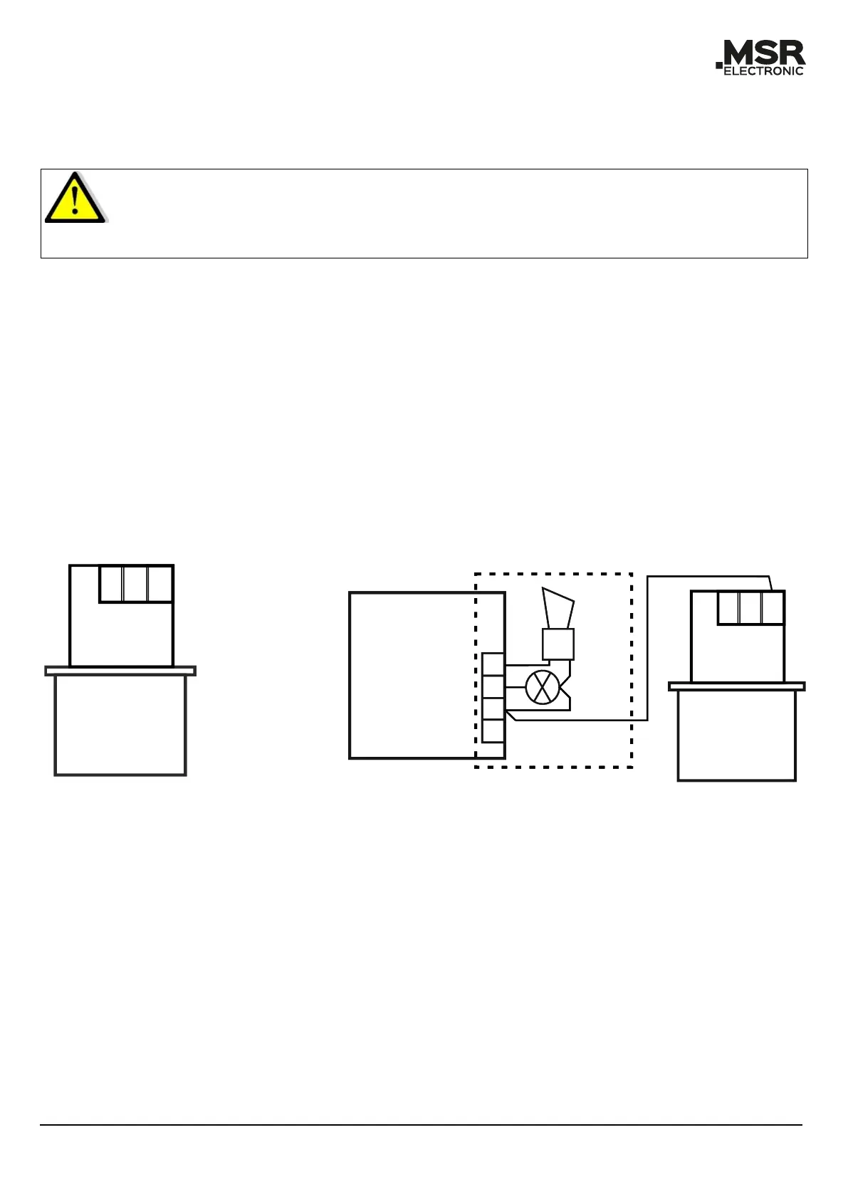
Caution:
SC2 Sensors are equipped with a reverse polarity protected connector (3-pin).
Do not plug it in by force.
Ensure correct positioning.
• Plug in the SC2 Sensor at the designated plug-in terminal of the Board (observe plug polarity).
The connector must engage.
• The Sensor’s plug-in terminals on the Boards are connected in parallel, so it is irrelevant to
which socket the SC2 is connected (exception: WSB2).
4.2 Terminal Connection (MC2)
• Open housing cover (optional).
• Insert cable from above, cut and strip it (optional).
• Connect it to the terminal (only 3-wire connection possible).
• For the 4–20 mA mode, please remove the built-in resistor (500 Ω) between terminals 2 and
3.
• Close cover (optional).
4.3 Registration of the Sensors SC2/MC2
Registration and addressing of the field bus address: See user manual of the SB2, MSC2, MSB2 and
WSB2 Boards.