Instead of the digital zero-point calibration, the zero-point calibration is carried out with a potenti-
ometer.
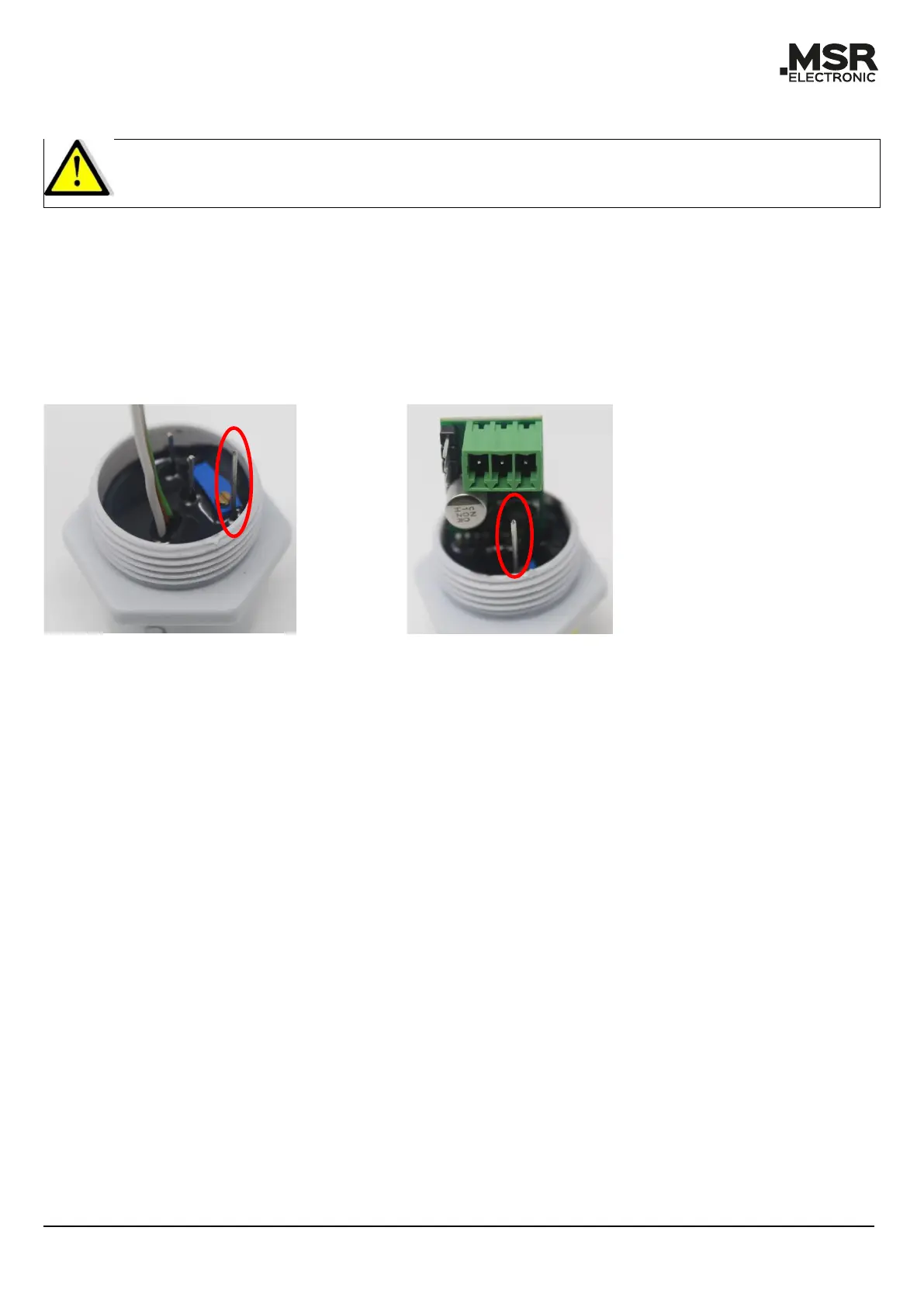
• Connect the multimeter (mV) to the test pin (marked in red in Figure 3 and Figure 4) and GND
(pay attention to the connection diagram of the respective Board).
• Measure voltage against ground (GND).
• Caution: It is mandatory to use the GND of the Board to prevent a ground loop.
• Set to 300 mV ± 1 % with the potentiometer.
6.2.2 Gain Calibration
• Open the test gas dialog (for PCE06 open the gain calibration dialog directly) and enter the
concentration of the test gas used (value between 30–90 %, for semiconductor sensors ex-
actly 50 % of the measuring range).
• Open gain calibration dialog.
• The current sensor element sensitivity is read out by “Display”.
• Apply test gas to the sensor head (flow rate and application time according to Table 4 to Ta-
ble 7, and output pressure 1 bar ± 10 %).
• After the application time has elapsed, the new gain factor is calculated by “Calculate”,
checked for plausibility and stored in the temporary memory. The current measured value is
output with the new gain factor and the display and sensor sensitivity are updated.
• The new gain factor is written into the sensor's memory by "Save"; only then is the gain cali-
bration completed. If the menu is left without saving, the original data is used for the meas-
ured value calculation.
For safety reasons, the calibration of the gain factor is limited. With a loss of sensitivity to 30 % re-
sidual sensitivity, calibration is no longer possible, from 40 % onwards an indication is already
given. The sensor must be replaced as soon as possible. It is required to document the successful
calibration with a protocol and to attach a label to the device containing the date for the next cali-
bration. Further information can be found in the instructions for use of the corresponding Board
and tool documentation.
If, in the case of semiconductor sensors, the set test gas is not reached in the display during the gain
calibration, an extended calibration must be carried out.