Clutch and Controls
7
Clutch Operation
1. Pulling the clutch control bale toward the handlebar
pulls the clutch cable.
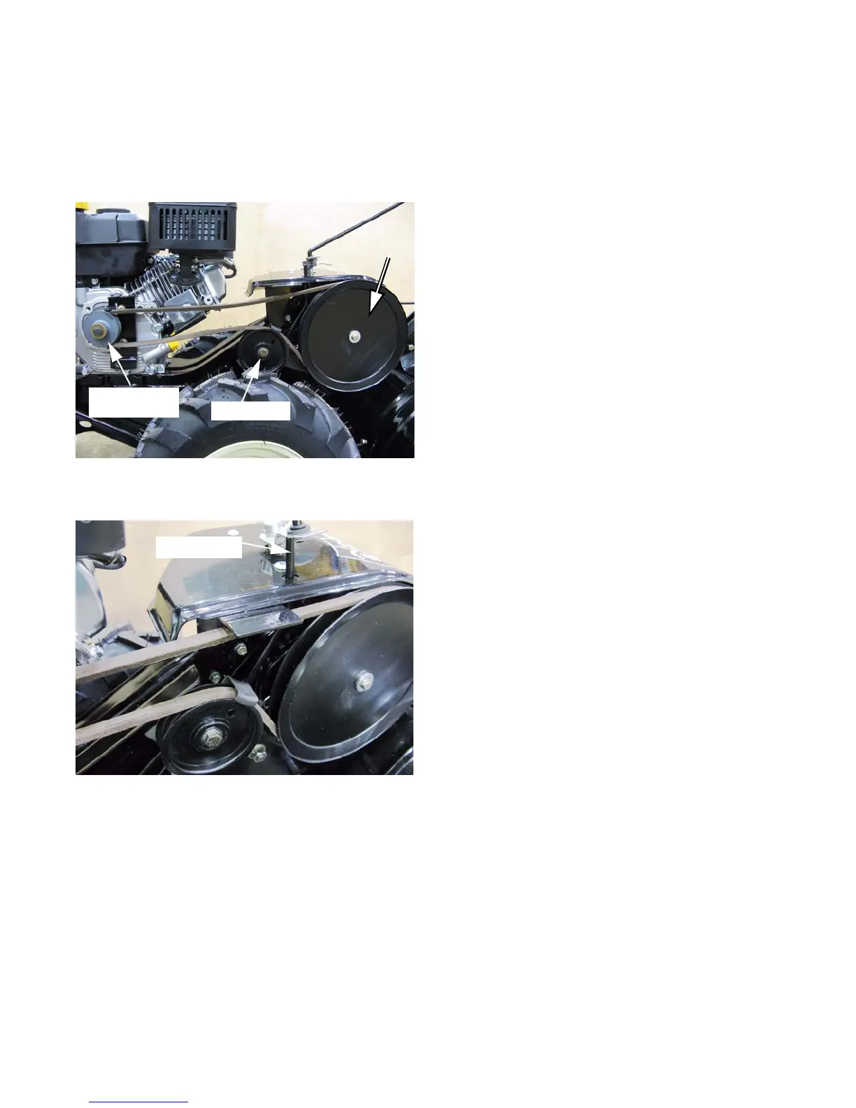
2. The clutch cable draws an idler pulley against the
bottom of a belt that runs from the engine crankshaft
pulley to the input pulley of the chain case.
3. The idler pulley tightens the belt, transferring drive
power to the chain case. See Figure 2.1.
4. There is an interlock pin connected to the idler pulley
bracket. See Figure 2.2.
• When the clutch is engaged, the pin prevents the
operator from shifting the tiller between Tines For-
ward and Tines Reverse operation.
• Shifting the tiller between different drive modes
while the clutch is engaged puts unusual loads on
internal chain case parts. The lock-out pin helps
prevent the customer from damaging the chain-
case.
Figure 2.1
Crankshaft
pulley
Input pulley
Idler pulley
Figure 2.2
Interlock pin
CHAPTER 2: CLUTCH AND CONTROLS
For Parts Call 606-678-9623 or 606-561-4983
www.mymowerparts.com
 Loading...