450 Series Tillers
40
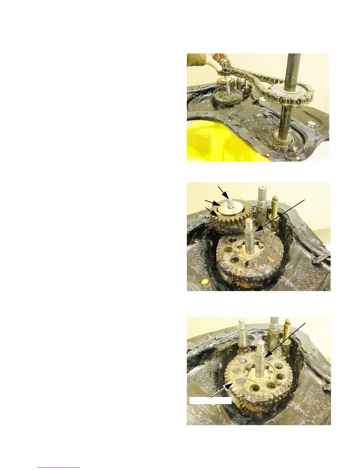
Main Shaft Assembly
1. Remove the tine shaft and the top gear (tine drive
gear) from the main shaft, as described in the Tine
Shaft Assembly section of this chapter.
See Figure 5.37.
2. There is a washer between the top gear on the
counter shaft and the upper half of the chain case
housing. It may be on the counter shaft, or it may
have come off with the upper housing. Confirm its
location and remove it.
3. Lift the top gear (tines forward drive gear) off of the
counter shaft.
NOTE: The edges of the teeth on tines forward drive
gear differ from one side to the other:
• One edge is straight cut, the other is beveled.
• The beveled edges make it easier for the input
pinion gear to slide into engagement with the
tines forward drive gear.
• The tines forward drive gear is installed with the
beveled edge facing down.
4. Lift the tine drive gear off of the main shaft.
See Figure 5.39.
NOTE: There is a paired gear set on the main shaft:
• Tine drive gear on top
• Wheel drive gear below
NOTE: Tine gear orientation: the tine gear has a flat
side and a recessed side:
• The recessed side faces up when it is correctly
installed.
• Notches in the teeth of the tine drive sprocket
register against the step in the tine drive gear.
• The flat side rests on a washer that separates
the tine drive gear from the wheel drive gear.
Figure 5.37
Tine shaft, chain
and sprocket
removal
Figure 5.38
ounter sha
t
Washer
Gear
Main shaft
Figure 5.39
Main shaft
Tine drive gear
For Parts Call 606-678-9623 or 606-561-4983
www.mymowerparts.com
 Loading...