Chain Case
27
Wheels Forward
1. If the operator moves the control lever one notch up
from the Neutral position, the shift fork will move to
the next detent up from Neutral.
2. The shift fork will raise the input spur gear to a point
where the upper set of teeth engage only the lower
half of the paired wheel drive and tine drive gears on
the main shaft. See Figure 5.5.
3. The input spur gear will drive the wheel drive gear on
the main shaft in the opposite direction that the input
shaft is turning. The main shaft gear will turn C
ounter
C
lock Wise.
4. The wheel drive transfer gear transmits power from
the lower half of the paired gears on the main shaft to
the wheel drive reduction gear. The wheel reduction
drive gear will turn C
lock Wise. See Figure 5.6.
5. The wheel drive reduction gear turns a sprocket to
drive the wheel axle via chain.
6. When the wheel axle turns the same direction as the
input shaft, the tiller will move forward. The tines
should not rotate.
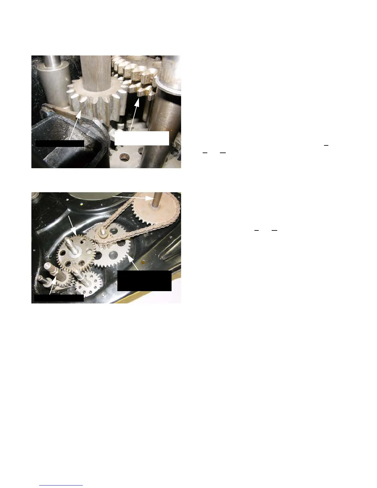
Figure 5.5
Wheel drive gear
on main shaft
Input spur gear
Figure 5.6
Wheel axle
Wheel drive gear
on main shaft
(CCW)
(CW)
Input shaft (CW)
Wheel drive
reduction gear
and sprocket (CW)
For Parts Call 606-678-9623 or 606-561-4983
www.mymowerparts.com
 Loading...