Chapter 7: Ignition System
78
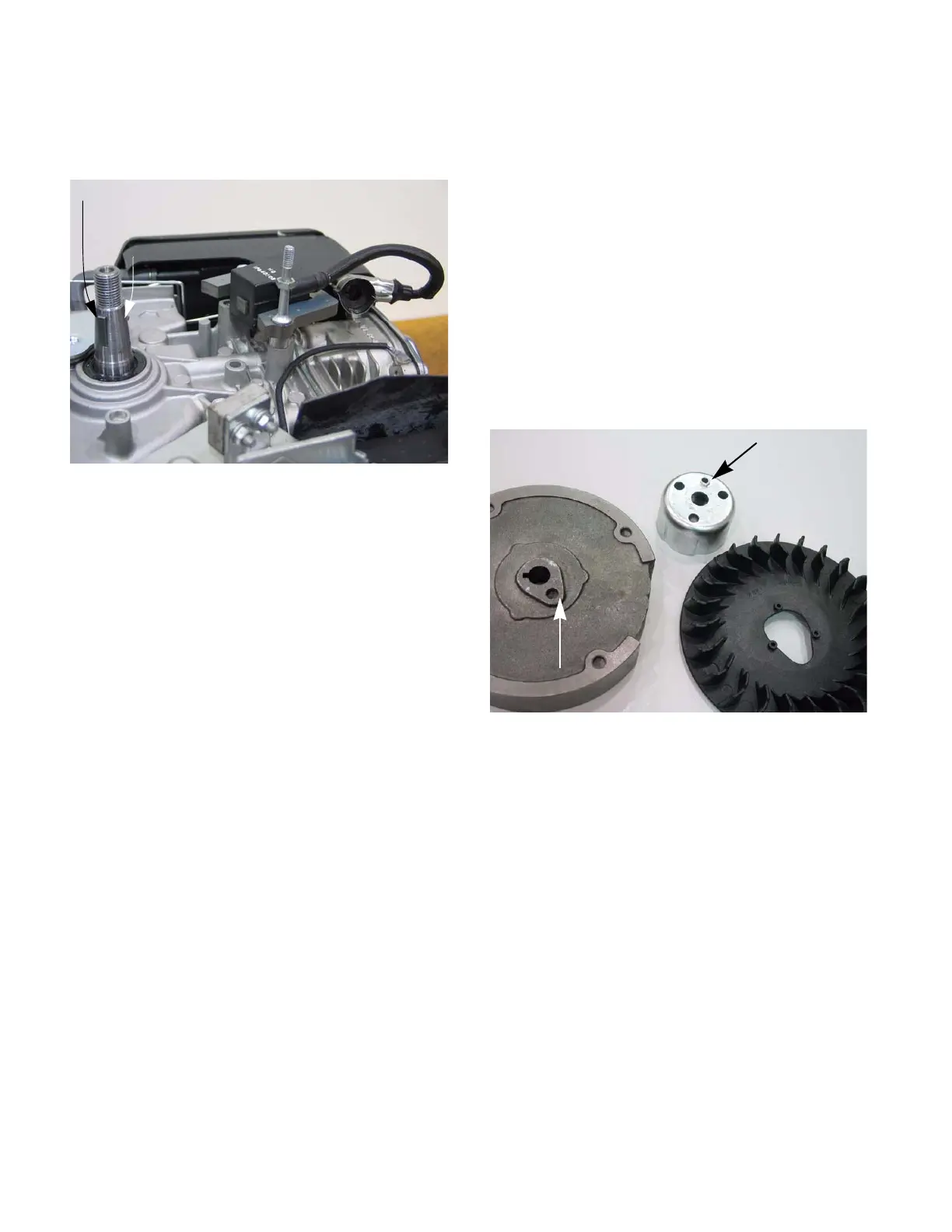
2c. Inspect the key, keyway, and tapered mating
surfaces of the flywheel and crankshaft.
See Figure 7.27.
NOTE: If the key is damaged it must be
replaced. If there is damage to the crankshaft
key way, the engine must be short blocked
because crankshafts are not available as a ser-
vice part.
2d. On installation, confirm that the key is prop-
erly seated (the flat of the key parallel with
the threaded section of the crankshaft) in
the key-way, and that the tapers are fully
seated. Key or keyway failure may result
from improper seating.
IMPORTANT: The taper in flywheel and the on
the crankshaft must be clean and dry. The fly-
wheel is held in place by the friction fit between
the flywheel and the crankshaft, not the key. The
key is only to guide the flywheel to the proper
position until it is torqued down.
2e. Install the flywheel nut to a torque of 47-52
ft-lbs. (64-70 Nm).
NOTE: If the engine has a cast iron flywheel;
install a starter cup by placing the starter cup on
the flywheel. Allow the protrusion on the bottom
of the starter cup to rest inside the dimple in the
flywheel with the plastic fan trapped in between
the two. See Figure 6.28.
2f. Adjust the air gap by following the steps
described in the previous section of this
chapter.
2g. Reassemble the engine.
2h. Test run the engine before returning to ser-
vice.
Figure 7.27
Key flat parallel to the threads
Taper
Figure 6.28
Starter cup protrusion
Flywheel dimple
www.mymowerparts.com
For Discount White Outdoor Parts Call 606-678-9623 or 606-561-4983
 Loading...


