Starter and Charging System
69
Charging system testing
To test the charging system:
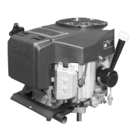
1. Locate the connection between the engine harness
and the main harness of the machine.
See Figure 6.37.
2. Start the engine and run it at full throttle.
3. Check the engine RPMs.
NOTE: The engine must be at 3,300 RPMs to test the
alternator output.
4. Connect the black (-) lead of a digital multimeter to a
good ground on the engine.
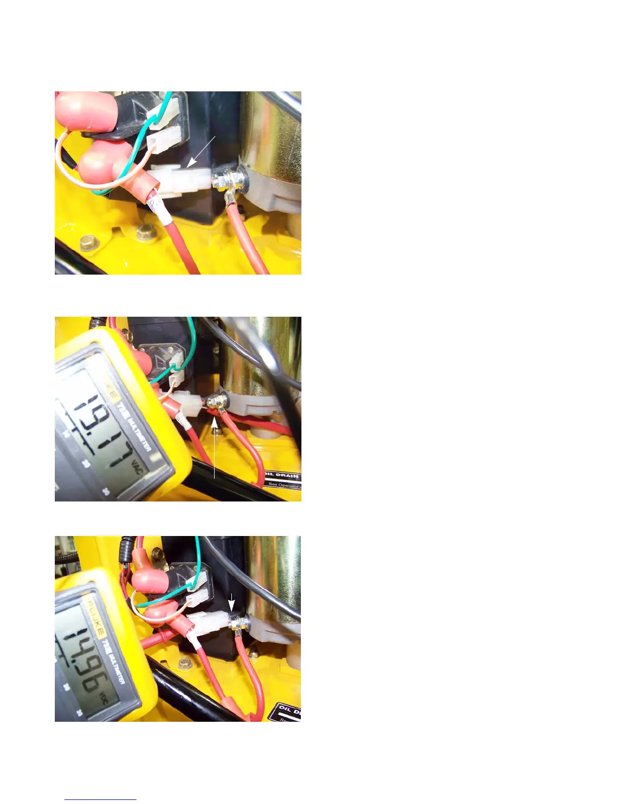
5. Set the multimeter to read AC voltage.
6. Back probe the orange wire in the charger harness
with the red (+) lead of the multimeter.
See Figure 6.38.
7. The multimeter should read a voltage of 11 - 20 Vac.
NOTE: If the AC voltage is too low, remove the flywheel by
following the procedures described in Chapter 7:
Ignition System and check the internal magnets. If
they are still magnetic, replace the stator.
8. Set the multimeter read DC voltage.
9. Back probe the purple wire of the charger harness.
See Figure 6.39.
NOTE: Will be a different color on the equipment side of
the harness connection.
10. The multimeter should read 13.75 - 15.5 Vdc.
Figure 6.37
Engine harness
connector
Figure 6.38
Positive probe
Figure 6.39
Purple wire
www.mymowerparts.com
For Discount Cub Cadet Parts Call 606-678-9623 or 606-561-4983
www.mymowerparts.com
For Discount Cub Cadet Parts Call 606-678-9623 or 606-561-4983

 Loading...