Ignition System
77
Flywheel
The flywheel holds the magnets. These magnets induce a field in the module which in turn produces a spark. It
also controls the timing of the ignition system by controlling when the magnets are introduced to the module.
A sheared flywheel key will throw off the ignition timing. Sheared keys are uncommon on MTD engines. If one is
found, check the crankshaft and flywheel for damage.
To Remove and/or inspect the flywheel and key:
1. Remove the blower/air filter housing by following the
steps procedures in Chapter 3: Air Intake System.
2. Remove the ignition module by following the proce-
dures described in the module section of this chapter.
3. Block the piston to prevent the crankshaft from turn-
ing by:
3a. Remove the spark plug.
3b. Insert approximately 3.3’ (1 m) of starter rope in
the spark plug hole.
NOTE: Leave part of the rope sticking out of the engine so
that the rope can be removed later.
- or -
3c. Use a strap wrench to hold the flywheel.
4. Remove the flywheel nut, using a 23mm wrench.
NOTE: The three screws needed for the puller are 6mm x
1.0, 60mm in length or longer depending on the
puller used.
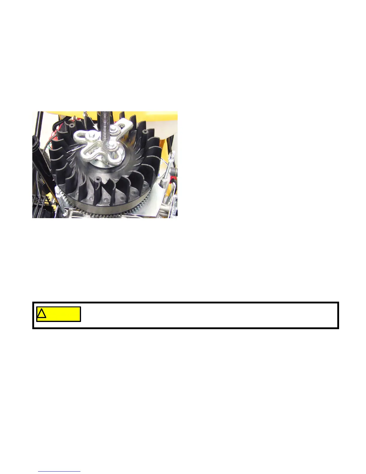
5. Remove the flywheel by using a harmonic balancer
puller.
See Figure 7.6.
NOTE: It is not necessary to remove the plastic fan and
support washer to install the puller.
NOTE: Never strike the crankshaft with a hammer.
6. Inspect the key, keyway, and tapered mating surfaces of the flywheel and crankshaft.
NOTE: If the key is damaged, the crankshaft must be replaced.
NOTE: On installation, confirm that the key is properly seated (the flat of the key parallel with the threaded
section of the crankshaft) in the keyway, and that the tapers are fully seated. Key or keyway failure may
result from improper seating.
IMPORTANT: The tapers in flywheel and on the crankshaft must be clean and dry. The flywheel is held in
place by the friction between the flywheel and the crankshaft, not the key. The key is only to
guide the flywheel to the proper position until it is torqued down.
7. Install the flywheel nut to a torque of 81 - 85 ft-lbs (110 - 115 Nm).
8. Install the module by following the procedures described in the module section of this chapter.
9. Reassemble the engine.
10. Test run the engine before returning to service.
Figure 7.6
Harmonic balance puller
! CAUTION! CAUTION
If the flywheel shows any signs of physical damage such as cracks, broken vanes (if equipped),
or a damaged keyway, replace it. A damaged flywheel poses a threat of a burst failure. Burst
failures are extremely hazardous to surrounding people and property.
www.mymowerparts.com
For Discount Cub Cadet Parts Call 606-678-9623 or 606-561-4983
www.mymowerparts.com
For Discount Cub Cadet Parts Call 606-678-9623 or 606-561-4983

 Loading...