10
NOTICE
Take care to mount the sensor in an axially parallel position to
avoid damage to magnet and sensor.
≤ 5
(≤
M5
Alternative:
If only limited space is available, the profile sensor can be mounted
also via the T-rail in the profile bottom using an T-slot nut M5
(part no. 401 602) or a sliding block (Fig. 11).
Installation of ET-P (profile sensor)
The position sensor can be installed in any position. Normally,
the sensor is firmly installed and the position magnet is fastened
to the mobile machine part. Thus it can travel along the sensor profile.
The sensor is fitted on a flat machine surface using the mounting
clamps (Fig. 10). A length-dependent number of these clamps are
delivered with the sensor and must be distributed over the profile
at regular distances. For fastening we recommend using M5×20
screws (DIN 6912) that should be tightened with a fastening torque
of 5 Nm.
Fastening torque: 5 Nm
50
9.5
(0.37)
Bore Ø 5.3
14.6
Fig. 10: Mounting clamps (part no. 400 802) with cylinder screw M5×20
Fig. 11: T-slot nut M5 (part no. 401 602)
Temposonics
®
ET Analog ATEX / IECEx / CEC / NEC / CCC Certified
Operation Manual
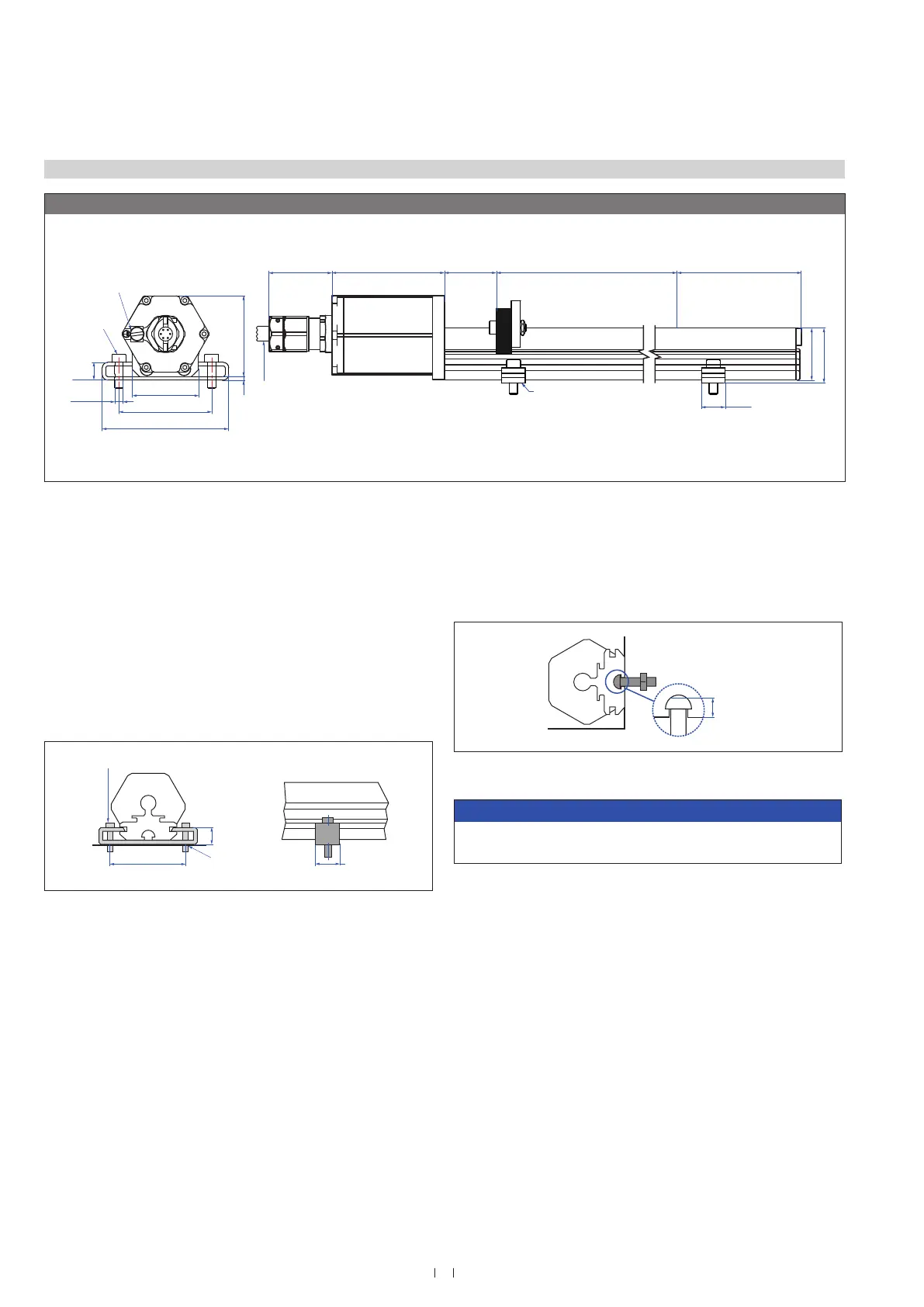
4.3 Styles and installation of Temposonics
®
ET (profile sensor)
Controlling design dimensions are in millimeters and measurements in ( ) are in inches
ET-P, example: Version A / N
Magnet
68 (2.68)
9.5 (0.37)
50 (1.97)
2 (0.08)
Ø 5.3
(Ø 0.21)
35.6 (1.4)
e.g. for
M5 or
#10 screws
housing
55
(2.17)
~34
(~1.34)
Null zone
28
(1.1)
Dead zone
66
(2.6)
14.6
(0.57)
Adjustable mounting clamp
Stroke length
50…3000
(2…118)
Teflon
®
cable: Ø 7.6 (0.3)
Silicone cable: Ø 7.2 (0.28)
Ground
44,4 (1,75)
28 (1.1)
30.2 (1.2)
Controlling design dimensions are in millimeters and measurements in ( ) are in inches
Fig. 9: Temposonics
®
ET (profile sensor) with U-magnet

 Loading...


