21
Temposonics
®
ET Analog ATEX / IECEx / CEC / NEC / CCC Certified
Operation Manual
5.2.3 Programming kit, part no. 254 555
The PC programmer is a hardware converter between sensor and
serial PC interface. It can be used for adjusting sensor parameters via
computer and the MTS Sensors programming software, see also “5.2.4
Setting examples for programming tools” on page 23. The software
for reading and adjusting the sensors requires a Windows computer
with a free USB port. You can adjust the following parameters:
• Start / end position (min. 25 mm (1 in.) between new setpoints)
• Output signal if errors occur (e.g. no position magnet)
Fig. 31: Active measuring range
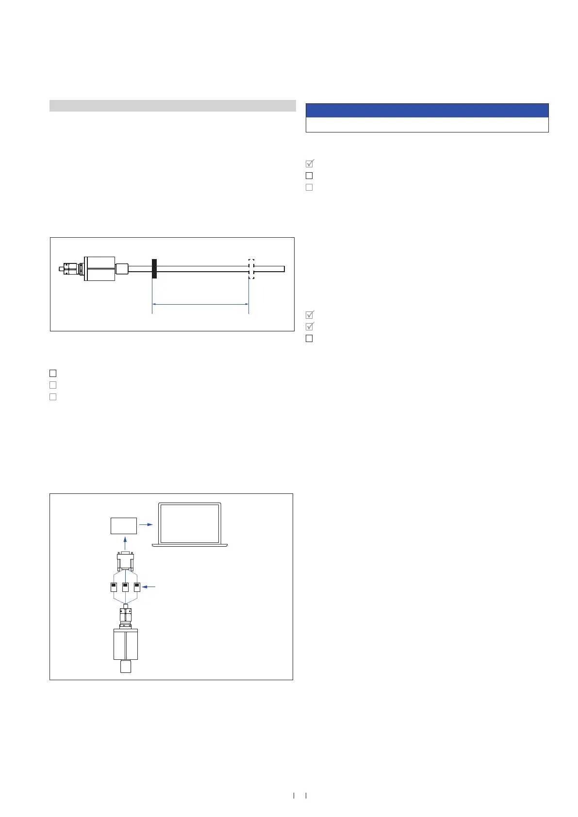
Fig. 32: Connect PC programmer
Step 1: Connect PC programmer
Step 2: Install software
Step 3: Start programm
• Connect the PC programmer with the sensor via the corresponding
adapter cable
• Connect the PC programmer to a USB port of the computer
• Connect the power supply via connector
The outer contact of the connector is 0 V (ground), the inner
contact is 24 VDC
NOTICE
Never connect / disconnect the sensor when voltage is applied.
Download the current software version from www.mtssensors.com.
Copy the program MTSAnalogConfigurator.exe to your computer and
start the program. The program now displays a list of available COMs.
A free COM port is selected. The COM port, which was chosen, is dis-
played in the Device Manager. If a connection fails, it could be a missing
driver. In this case, download and install the USB serial converter driver
from www.mtssensors.com.
After starting the program, the user interface of the connected sensor
with its adjustable parameters will open (Fig. 33).
Step 1: Connect PC programmer
Step 2: Install software
Step 3: Start program
Step 1: Connect PC programmer
Step 2: Install software
Step 3: Start program
Active measuring range
Stroke length
0 % 100 %Magnet position
Output 1: Position
GY WH BN
WH BN
GY
USB
converter
Spring terminal
 Loading...


