22
Temposonics
®
ET Analog ATEX / IECEx / CEC / NEC / CCC Certified
Operation Manual
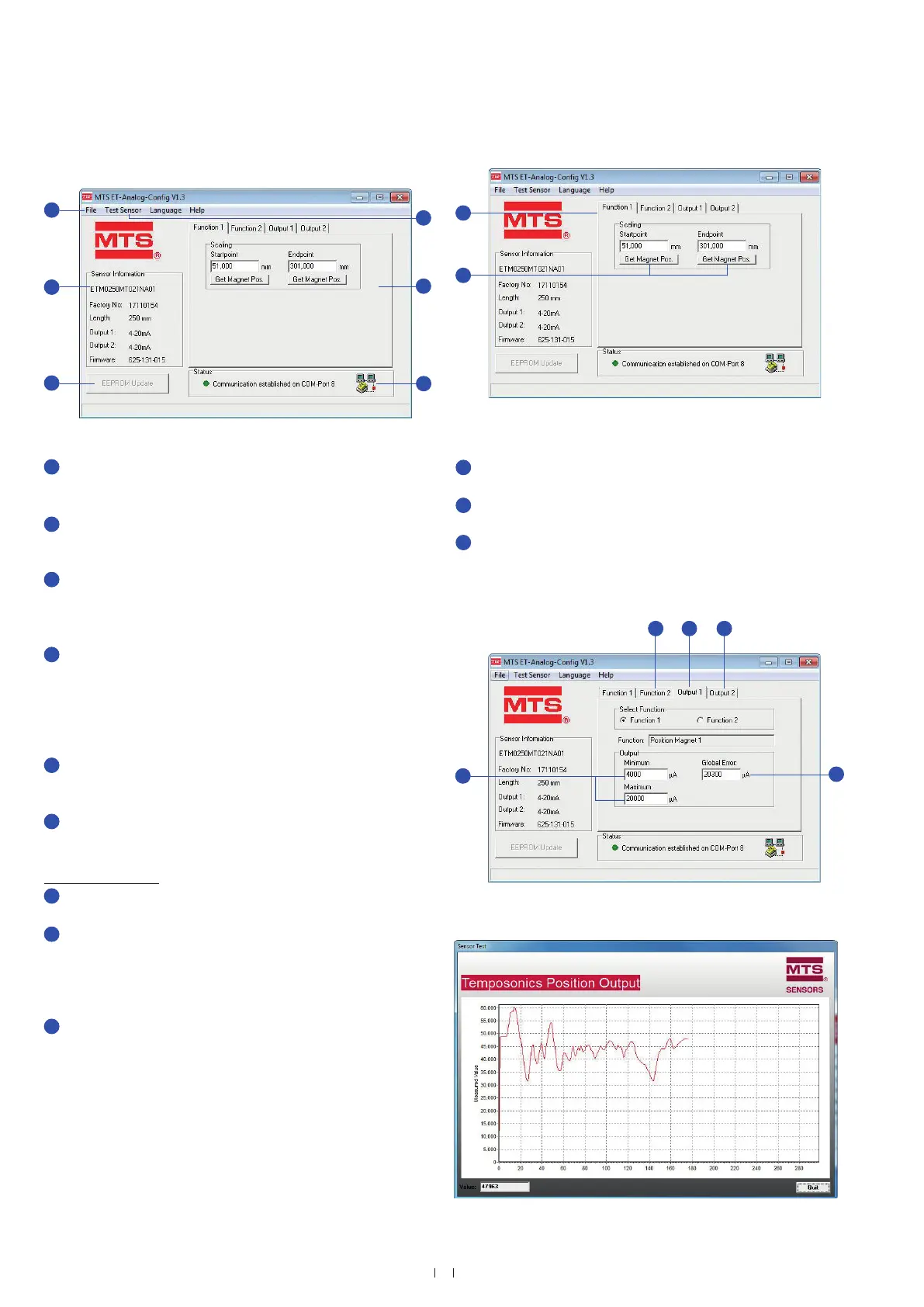
In the File menu the sensor configuration can be saved on hard
disk, printed out or loaded into the sensor
4
. Moreover, this menu
permits returning to the factory setting (Fig. 33).
Sensor Information contains the invariable sensor parameters,
which were read in automatically when connecting the sensor.
(Fig. 33).
Any changes which were made are shown with dark background.
By clicking on EEPROM Update the altered parameters are stored
in the sensor permanently. Subsequently, the stored values are
displayed again with a white background (Fig. 33).
Menu Test Sensor provides a data display (Fig. 36), which shows
the absolute position of the position magnet. Compared with the
sensor measuring rate, the serial data transmission between
sensor and PC is relatively slow, i.e. not every measured value can
be displayed. For this reason, only every 50th measurement value
appears in the diagram.
The control tabs of the main display section permit allocation
of functions to the sensor outputs. The measuring range of the
functions will be determined in Scaling (Fig. 33).
Status indicates that the sensor is connected successfully (Fig. 33).
Dialog field with tabs
Determine the measuring range with Startpoint and Endpoint via
tab Function 1 (Fig. 34).
The current magnet position can be stored via buttons Get Magnet
Pos.. The measuring direction changes, when the value of the
startpoint is higher than the value of the endpoint. Independent of
the measuring direction, the minimum measuring distance is
25 mm (Fig. 34).
The field Output Minimum indicates the current or voltage
value which should be output at the startpoint of the selected
function. The output value pertaining to the endpoint must be
specified in field Output Maximum (Fig. 35).
Fig. 33: MTS ET-Analog-Config V1.3, Function 1
Fig. 34: Dialog field with tabs
On tabs Function 2, Output 2, the second analog output can
be set (Fig. 35).
On tab Output 1 the corresponding analog output signals can be
allocated (Fig. 35).
Unless a position magnet is missing or if it is in the sensor's
dead zone, i.e. out of measuring range, Global Error is output.
The error value can be adjusted within −0.7…20.3 mA or
−0.4…10.4 VDC (Fig. 35).
Fig. 35: Example of tab controls
4/ Only sensor configurations with the same serial number are permissible
MTS ET Analog software user interface
1
2
3
4
5
6
7
8
9
10
12
11
1
2
3
5
6
7
8
10
11
10
12
9
4
Fig. 36: Data display
 Loading...


