11
NOTICE
Mount ring magnets and U-magnets concentrically.
Mount block magnets centrically over the sensor rod or the sensor
profile. The maximum permissible air gap must not be exceeded
(Fig. 13/Fig. 14). Take care to mount the primary sensor axis in
parallel to the magnet path in order to avoid damage to the carriage,
magnet and sensor rod/sensor profile.
Fig. 12: Typical use of magnets
Mounting ring magnets, U-magnets & block magnets
Install the magnet using non-magnetic material for mounting
device, screws, spacers etc.. The magnet must not grind on
the sensor rod. Alignment errors are compensated via the air gap.
• Permissible surface pressure: Max. 40 N/mm
2
(only for ring
magnets and U-magnets)
• Fastening torque for M4 screws: 1 Nm; use washers, if necessary
• Minimum distance between position magnet and any magnetic
material has to be 15 mm (0.6 in.) (Fig. 15).
• If no other option exists and magnetic material is used,
observe the specified dimensions (Fig. 15).
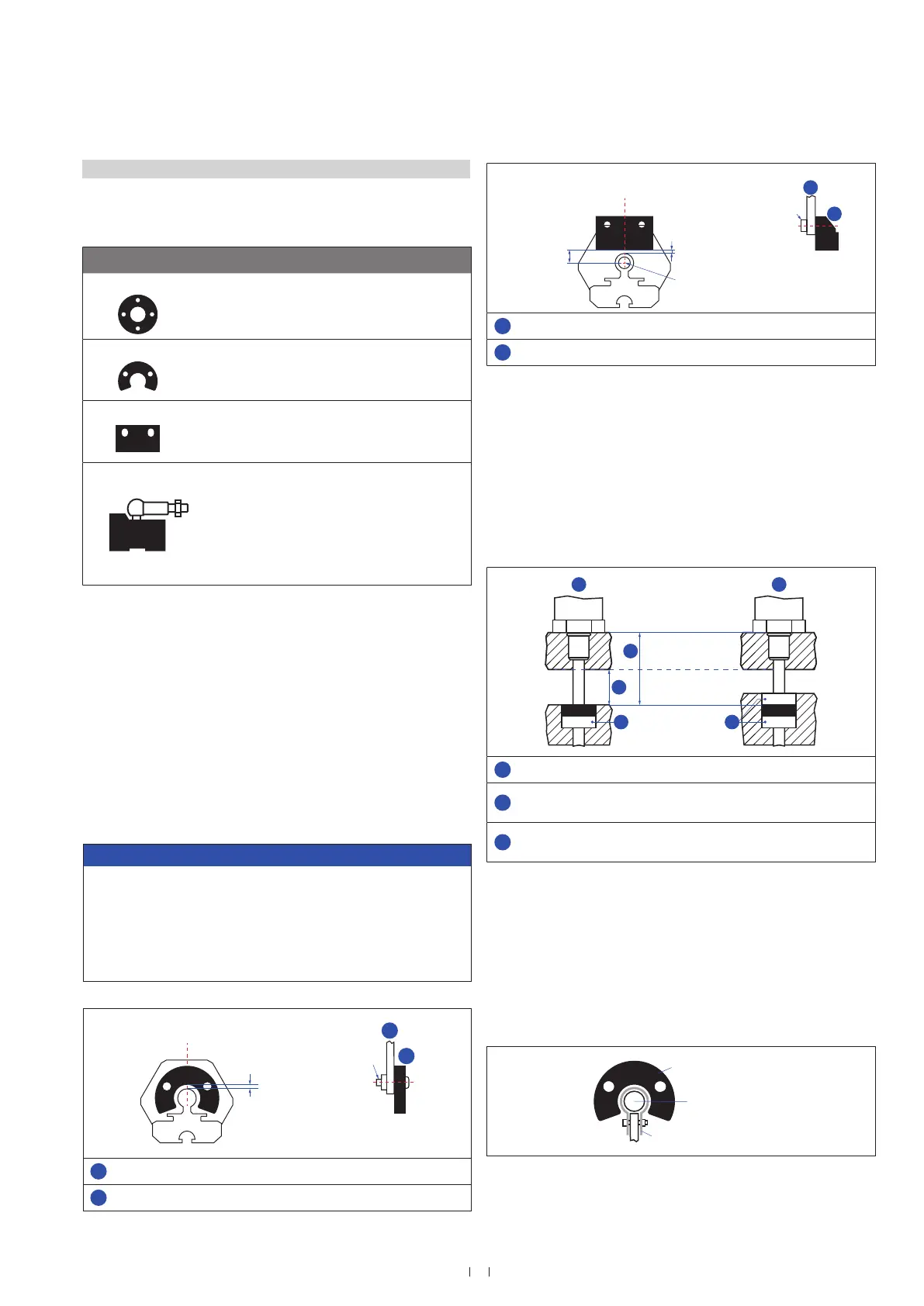
Fig. 13: Mounting of U-magnet (part no. 251 416-2 or part no. 201 553)
M4
1
2
Air gap
of U-magnet
Part no. 251 416-2:
1.75 ±1 (0.07 ±0.04)
1
U-magnet
2
Non-magnetic mounting plate
Magnet Typical sensors Benefi ts
Ring magnets
Rod model
(ET-F/-W/-M/-S)
• Rotationally symmetrical
magnetic fi eld
U-magnets
Profi le &
rod models
(ET-P/-F/-W/-M/-S)
• Height tolerances can be
compensated, because the
magnet can be lifted off
Block magnets
Profi le &
rod models
(ET-P/-F/-W/-M/-S)
• Height tolerances can be
compensated, because the
magnet can be lifted off
Magnet sliders
Profi le models
(ET-P)
• The magnet is guided by the
profi le
• The distance between the
magnet and the waveguide is
strictly defi ned
• Easy coupling via the
ball joint
Rod sensors with stroke lengths ≥ 1 meter (3.3 ft.)
Support horizontally installed sensors with a stroke length from 1 meter
(3.3 ft.) mechanically at the rod end. Without the use of a support, rod
and position magnet may be damaged. A false measurement result is
also possible. Longer rods require evenly distributed mechanical support
over the entire length (e.g. part no. 561 481). Use an U-magnet (Fig. 16)
for measurement.
Magnet mounting with magnetic material
When using magnetic material the dimensions of Fig. 14 must
be observed.
A. If the position magnet aligns with the drilled piston rod
B. If the position magnet is set further into the drilled piston rod,
install another non-magnetic spacer (e.g. part no. 400 633) above
the magnet.
Sensor rod
Magnet
Magnet
1
2
3
Magnetic
material
3
1
Null zone, depends on sensor model
2
Distance between position magnet and any magnetic material
(≥ 15 mm (≥ 0.6 in.))
3
Non-magnetic spacer (≥ 5 mm (≥ 0.2 in.)) –
Recommendation: 8 mm (0.31 in.)
M4
2
1
8 ±2
±0.08)
Sensor element
Air gap: 3 ±2
(0.12 ±0.08)
of block magnet
1
Block magnet
2
Non-magnetic mounting plate
Fig. 14: Mounting of block magnet (part no. 403 448)
Fig. 15: Installation with magnetic material
Fig. 16: Example of sensor support (part no. 561 481)
Temposonics
®
ET Analog ATEX / IECEx / CEC / NEC / CCC Certified
Operation Manual
4.4 Magnet installation
Typical use of magnets
Controlling design dimensions are in millimeters and measurements in ( ) are in inches
 Loading...


